
nyanClock
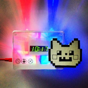
The nyanClock is a musical alarm clock made to resemble the ubiquitous internet meme, the Nyan Cat. Instead of sounding a harsh, annoying series of beeps that are common with most alarm clocks, the nyanClock will play a more pleasant version of the Nyan Cat theme song that I transcribed from this music box version.
I originally planned to complete the project in about two to three months before moving on to other projects. However, with the time it took to do the systems planning, parts selection, schematic capture, PCB layout, design review, PCB fabrication, board assembly, firmware writing, debugging and final assembly, the project took closer to seven months to complete. I had underestimated just how much time it would take to make something as simple as an alarm clock from scratch.
Overview
The nyanClock’s time is displayed using a seven-segment LCD. Three 5 mm LEDs serve as lights that turn on and off in sequence when the alarm is ringing. Three smaller side LEDs are placed to indicate the kind of setting that the user can change.
The clock is controlled by two user inputs, a top button and a rotary encoder. The top button will display the time or turn off the alarm if it is ringing. The rotary encoder allows the user to set the clock’s time and alarm. The user can enter the settings mode by pressing the encoder inwards. The alarm sounds come from a music instrument synthesizer IC which allows a greater variety of alarm customization. The nyanClock is powered by VBUS from a USB connection, although no USB functionality exists…for now.
System Design
Below is an overall block diagram of the nyanClock:
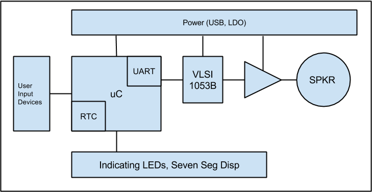
nyanClock Block Diagram
In the heart of the nyanClock is a microcontroller that keeps time, receives user inputs from the rotary encoder and top button, drives the seven-segment display and transmits MIDI messages to the VS1053B music instrument synthesizer IC during an alarm. The audio output of the VS1053B is fed into an amplifier which drives the speaker. Power is fed by the USB VBUS where it is then dropped to 3.3 V and 1.8 V busses using two LDOs.
The firmware is largely a state machine that runs one of the nyanClock’s three main states: idle, settings and alarm. Details about the firmware will be discussed further below.
Hardware

nyanClock PCB Layout
Microcontroller
The microcontroller is a PIC18F47J53 made by Microchip. It was chosen for its on-board RTC, lots of GPIOs and on-board flash memory (128 kb). This PIC also has USB capability in case any future revisions of the nyanClock implement a USB feature. A 32.768 kHz external crystal is connected to the Timer 1 external clock inputs which serves as the clocking for the RTC. The microcontroller drives the seven segment LCD display which is located on an external board and connected via FFC cable. The PIC’s UART peripheral is used to communicate musical data to the VS1053B IC. As the data structures containing musical score data can be quite large, I wanted a microcontroller with lots of flash memory.
Music Instrument Synthesis
The VLSI VS1053B chip is used to create musical instrument sounds. It also functions as a MP3 decoder but only the MIDI/synthesis functionality is used in the nyanClock. This is the same chip used in Sparkfun’s Music Instrument Shield.
Amplifier
The audio output of the VS1053B goes to a TI LM4906 1W, bridge configuration amplifier with selectable gain and an enabling pin which would be very useful in power conservation when the amplifier is not used, i.e. when the nyanClock is not ringing its alarm. The amplifier’s output is routed to an external connector which goes to an 8Ω speaker.
User Input
The nyanClock has two user inputs. A rotary encoder and an illuminated top button. The top button is connected to an external interrupt pin on the microcontroller while the rotary encoder is connected to pins that also trigger interrupts on state changes. To minimize the effects of switch debouncing, an RC circuit is placed near the switch/encoder connectors.
PCB and Fabrication
The PCB is a standard two-layer board which I had fabricated at OSH Park. Despite the good reviews that I have heard about them, I was a bit disappointed when I got the boards back and discovered that some of the drilling resulted in near-breakouts and some of the etching resulted in traces very nearly shorting out. A more detailed review of the boards can be found here. While I had a not-so-great experience with OSH Park, I will still continue to give them a try and see if I get better boards back.
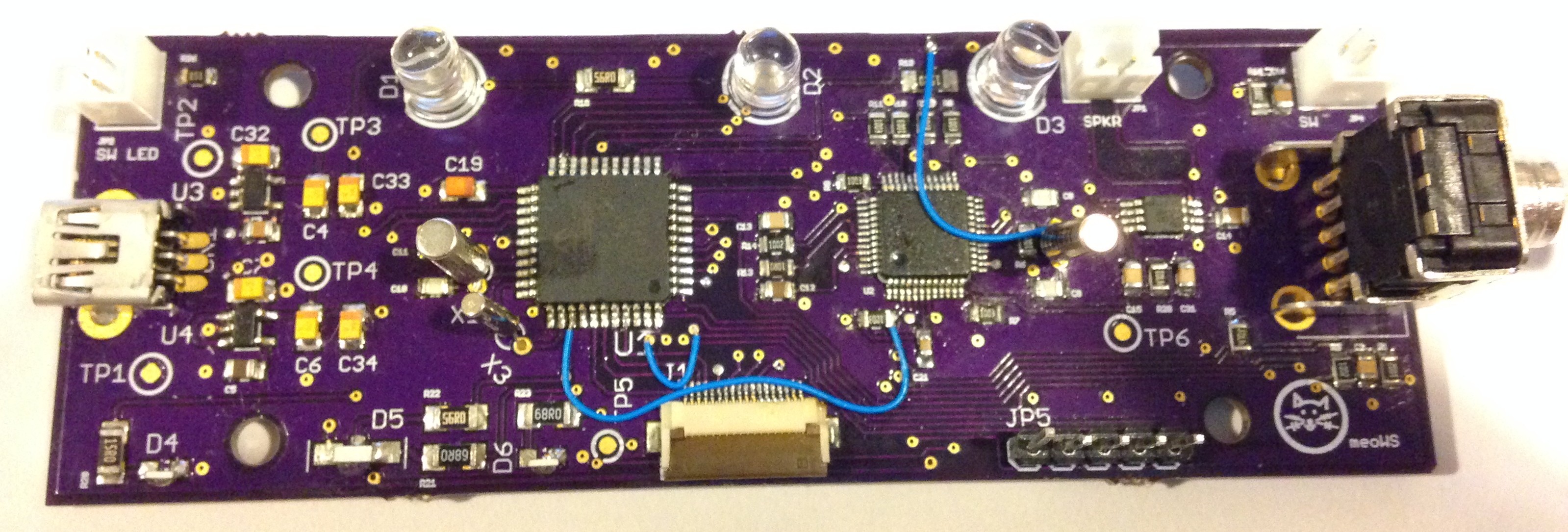
nyanClock board populated

Holes drilled in the enclosure, speakers and button added
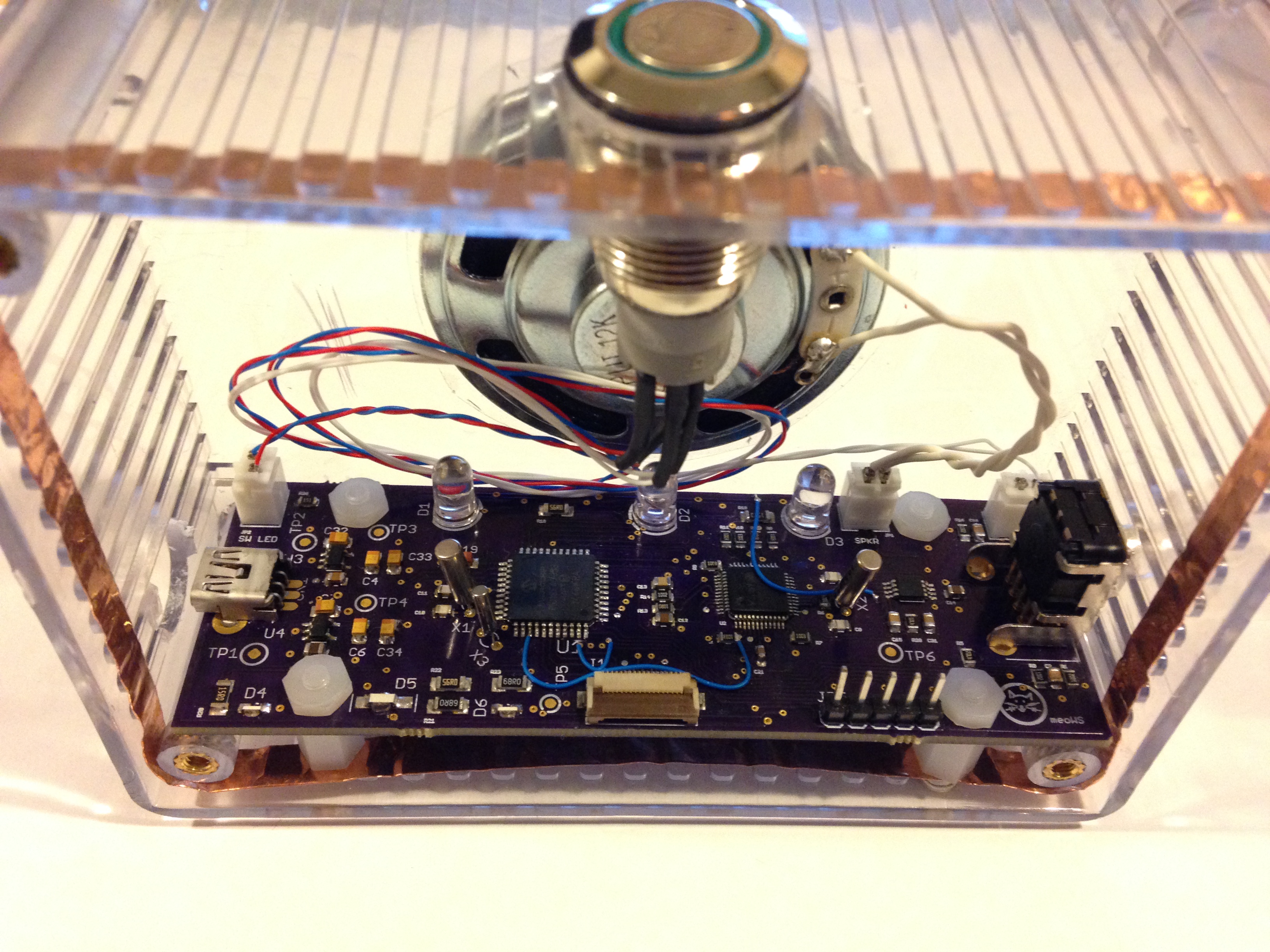
Board placed in enclosure and almost complete
Firmware
The nyanClock’s firmware is a relatively simple state machine containing three main states. One for when the clock is idling, another for allowing the user to change settings and the other for when the alarm interrupt is triggered. The firmware makes use of the RTCC peripheral library provided by Microchip to drive the RTC. Other blocks of code were written to work with user inputs, LEDs and display, music scoring and wrapping RTC functions such as setting time and alarm. The states are discussed detail below:
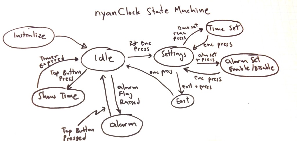
Simplified state machine
Idling State
Most of the nyanClock’s time will be spent here in the idling state. This state consists of an infinite loop that checks whether or not the user has pressed the top button or rotary encoder or if the alarm flag has been raised. If the user has pressed the top button then the state will show the current time. If the rotary encoder has been pressed, the nyanClock will move into the settings state. If the alarm flag has been raised (from an interrupt routine handling the RTCC alarm interrupt), then the nyanClock moves into the alarm state.
Settings State
The settings state is entered from idle when the rotary encoder is pressed inwards. From here, the nyanClock’s time and alarm can be set. The alarm can also be enabled or disabled in this state. The biggest challenge encountered here was writing a routine to handle the rotary encoder. The rotary encoder’s A and B pins are connected to PORTB on the microcontroller which will also trigger an interrupt whenever a rising or falling edge is detected. Each “click” of the encoder results in 4 changes in state (HIGH or LOW) for each pins, A and B, giving 8 changes in total. As the encoder clicks, interrupts are generated and the pin states are shifted into an 8-bit variable. When the encoder completes a click, the variable is examined and its value determines which direction the encoder was turned (clockwise or counter-clockwise). A post detailing how the rotary encoder is processed may be later made.
Alarm State
When the alarm from the RTCC module triggers an interrupt, an alarm flag is raised. This flag is repeatedly checked in the idle state and when the flag is high, the nyanClock enters the alarm state. The alarm, which plays the nyanCat song, cycles through a data structure that contains the musical score.
Finding a way to store a musical score was a little tricky. Past experiments such as this one called a “playNote” function for each and every note resulting in, without any compiler optimizations, enormous amounts of program memory used. For simple, monophonic phrases of music, one could get away with simply calling the playNote function N number of times. For more complex polyphonic scores however, something better is needed to make life easier.
The Score Data Structure
The “data structure” is really an array that stores musical data. It turns phrasing like this:
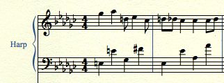
Into this:
[c] char score1[53][4] = {{78, ‘q’, 52, ‘q’},
{80, ‘q’, 64, ‘q’},
{74, ‘e’, 54, ‘q’},
{75, ‘e’, 0, ‘e’},
{0, ‘e’, 66, ‘q’},
{71, ‘e’, 0, ‘e’},
{74, ‘e’, 51, ‘q’},
{73, ‘e’, 0, ‘e’},
{71, ‘q’, 63, ‘q’},
{71, ‘q’, 56, ‘q’},
{71, ‘e’, 68, ‘q’},
{73, ‘e’, 0, ‘q’},
[/c]
The array, score1[][] is a structure that holds the entire musical piece, complete with all instruments/voices involved. In the above structure, two voices are at play so each score element is a sub-array of size 4. The sub-array holds two things for each voice: the note and its duration. As the alarm state runs, an index points to a sub-array where it is then passed off to a decoder and playback function. The index is incremented and the cycle continues:
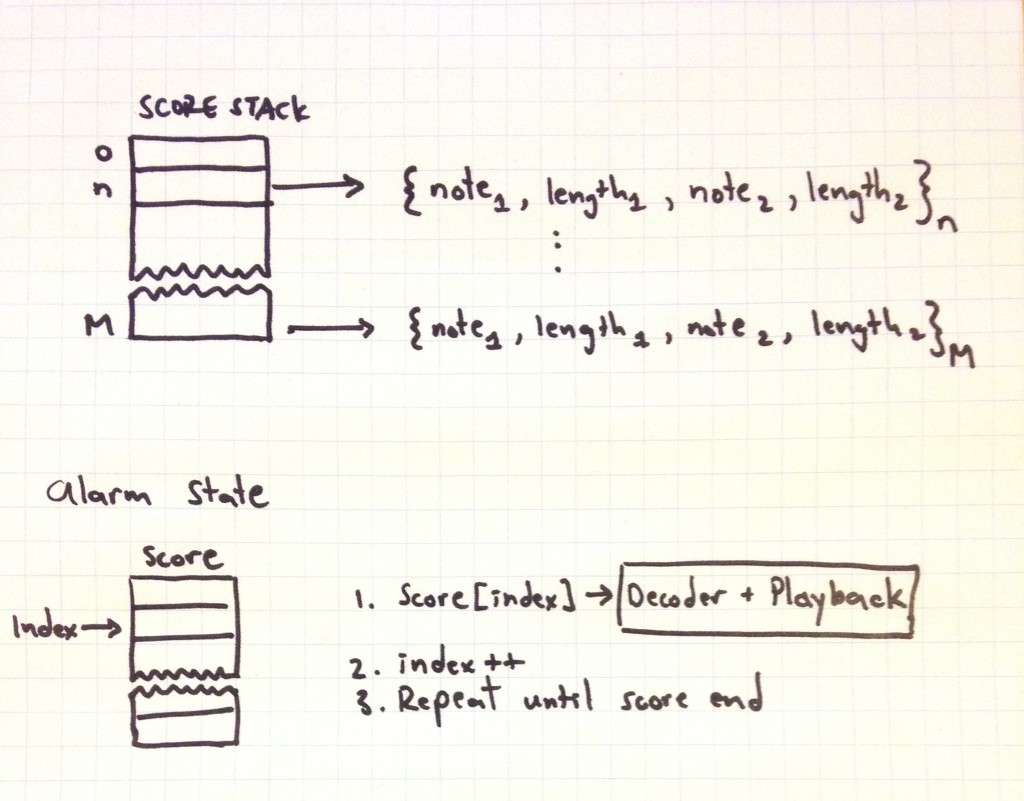
Score structure and playback routine
How the array is simple but can be tricky as the score is scaled larger. Below is an example phrase split to be entered into a score structure:
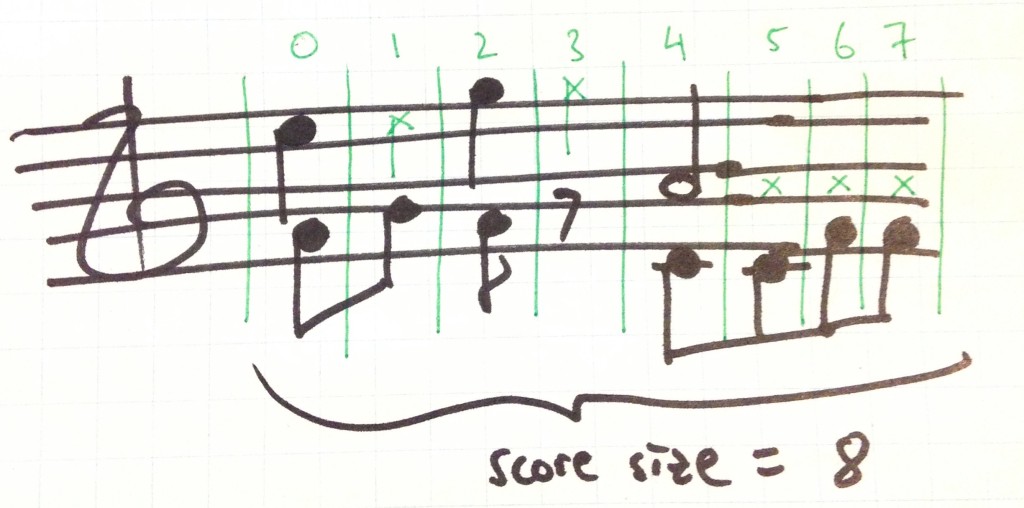
Example Phrase
As you look at the divisions, you will notice that the phrase is divided according to the shortest lengths of notes. This is to ensure that every note is covered during playback. In this example, there are a total of 8 divisions so the score size is 8. The “X” notes are “ghost notes.” These are “place holder notes” (passed as 0) that maintain the integrity of the sub-array while not playing anything. Ghost notes are typically found in cases like Division# 1, where a quarter note is played previously but there are two eight notes that must be played. Divisions# 0 to 3 will be coded like this:
[c]
{
{65, ‘e’, 76, ‘q’},
{67, ‘e’, 0 ,’e’),
{65,’e’, 79, ‘q’},
{0, ‘e’, 0, ‘e’}
}
[/c]
Notice that ghost notes will take on the duration of the note that is actually played. The durations are char types and the options are ‘w’, ‘h’, ‘q’, ‘e’ and ‘s’ for whole, half, quarter, eighth and sixteenth notes/rests respectively. The notes are numbers such that 60 is middle C.
While this method for score representation is more elegant than writing functions for each note, I’m still not satisfied with it and may continue to refine it. Dividing up the musical phrasing can be very time consuming and cumbersome. Additionally, the score structure is hard-coded for the number of instruments. I eventually would like to write a full data structure featuring dynamic score creation. For this project, the current structure does quite well.
Pitfalls
Most major pitfalls were hardware-related issues. Some of the highlights are described here:
PCB Layout and Assembly
The amplifier’s gain select control was routed to a GPIO that was shared with the USB peripheral. Unfortunately, due to not reading the data sheet closely enough, that particular pin was only able to function as an input and not an output. A bodge-wire was soldered to VCC to hard-wire the amplifier to provide maximum gain. Additionally, one of the indicator LEDs was met with the same fate so another bodge-wire was soldered to a free pin that was able to toggle on or off.
One of the things that I should have added to the board was an over-current protection circuit in case something shorted out.
While the LEDs do light up with no problems, a wise move would have been to add FET switches instead of driving the LEDs directly with the microcontroller pins. Many of the microcontroller’s pins can only source a maximum of 8 mA while an LED typically operates in the 20 mA range.
When populating the board, I noticed that soldering components that had one of their ends connecting to ground was quite difficult. It turned out that the traces to the ground pour were a little too thick so that there was a significant amount of heat thieving, making it more difficult to melt solder onto the pad.
ESD Issues
I noticed that sometimes the rotary encoder would not behave properly, either by not selecting the next setting or not registering a press. At times, the entire clock would reset. I had noticed that these issues mostly occurred when I was sitting on my bed and using the clock so I attributed these observations to ESD issues.
It turns out that the plastic used in the enclosure likes to generate and attract lots of static electricity. The fact that the seven-segment was adhered to the plastic cover also didn’t help the situation. It would have been very beneficial to add TVS diodes to the FFC connections going to the display. It would also have been useful to add them by the rotary encoder. One of my colleagues suggested that adding some copper tape around the inner perimeter, close to where the cover meets the enclosure body and then grounding the tape would help dissipate the static. After adding the tape, I found that these issues occurred much less frequently.

Copper tape for added ESD resistance
Ending Notes
Overall, this has been a fun project to work on and I did learn more in electronics and firmware design and even a bit of product design. I’m happy to have made an alarm clock that wakes you up in a more pleasant way. I am also happy to have had some great help along the way as my friends and colleagues looked over my layout, assembly and my not-so-great coding style.
Now, on to other projects…