
Optimizing Audio Code
This post is about squeezing more performance from your microcontroller. If you followed the FIR filter and reverb posts, you will have noticed that we needed to enable compiler optimizations to keep the audio processing time low enough to ensure that all incoming buffers will get processed in a timely fashion – i.e. causing no glitches or other artifacts in the output audio.
While the compiler is particularly smart when it comes to optimization, there are some things that it can miss that you as the programmer can add. Before we get into optimization techniques however, we need to talk about measuring performance.
Measuring Performance
There is something very important that we need to get out of the way first. If you’re going to remember only ONE thing from this post, it’s this: When first writing your code, do not begin to immediately add optimizations. To quote Donald Knuth, “Premature optimization is the root of all evil.” You can waste a huge amount of time optimizing a block of code only to realize that the execution time of the block, had it been unoptimized, is insignificant. Write your “brute force” code first and then measure the performance of your code to strategically identify areas for optimization!
In addition to not prematurely optimizing code, it’s worth mentioning that compilers are really smart. Often, it can be smarter than us. Sometimes when we try to be clever, the resulting performance can be worse than had we just let the compiler do the optimization for us. But how can we tell that what we are doing is working? That is where profiling comes in.
Even if we don’t plan on making code optimizations, it’s still important (especially in audio development) that we understand how long certain blocks of code are taking to execute. Here are some methods of measuring performance for bare-metal systems.
Logic Analyzers and Oscilloscopes
This, in my opinion, is possibly the best and simplest way of measuring performance. It involves toggling a GPIO pin high (or low) before entering the code block you want to profile. When exiting the code block, the pin is toggled back low (or high).
//  The GPIO toggle code is specific to the Silicon Labs EFM32PG12 microcontroller
//  If you are using a different manufacturer, you should be able to find
//  similar libraries (e.g. STM32 has a HAL library that includes GPIO toggles)

//  Assume that there is some code that adds audio data to this array
float audioBuffer[BUFFER_SIZE]

int main() {

  //  Initialize GPIO pin (PA0) used for profiling and set low
  GPIO_pinModeSet(gpioPortA, 0, gpioModePushPull, 0);
  GPIO_pinOutClear(gpioPortA, 0);

  while(1) {
    //  Apply some processing to the audio buffer (what kind is irrelevant in this case)
    //  We just want to profile this block of code!
    GPIO_pinOutSet(gpioPortA, 0);  //  Set pin high

    applyFilterToAudioBuffer(audioBuffer, BUFFER_SIZE);

    GPIO_pinOutClear(gpioPortA, 0);  //  Set pin back low
  }
  return 0;
}
Here, we want to know how long applyFilterToAudioBuffer() takes to process the buffer of samples in audioBuffer. When entering the block, we set the GPIO pin high and then set it back low when exiting. When we connect an oscilloscope or logic analyzer to this pin, we see the following pulses resulting from the function applyFilterToAudioBuffer() being endlessly called:
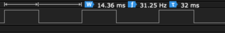
We see that the block takes 14.36 ms to execute. Is this good or bad? It honestly depends on what is being made. In this particular case, CPU time is largely divided between rendering graphics and audio. 16 msec is budgeted towards audio processing so this code takes about 90% of the budget.
If you plan to do a lot of embedded programming and do not have a logic analyzer, I highly recommend investing in one. They will save you so much time and headaches! This logic analyzer even has an analog channel to measure your analog signals!
Toggling GPIOs is simple and it gives a pretty good idea of the time taken for applyFilterToAudioBuffer() to execute. There is some overhead to calling GPIO_pinOutSet() and GPIO_pinOutClear() so the results are not 100% accurate. If you are using hardware abstraction libraries (HAL) for your microcontroller, be aware of what is going on in the GPIO functions. If there are a lot of other function calls and code executed, consider modifying the GPIO registers directly to keep overhead to a minimum!
Hardware Timers
Don’t have an oscilloscope or logic analyzer or don’t have free GPIOs? You can still measure performance by using a hardware timer!
//  Again, the HAL functions used here are specific to the EFM32PG12
//  You will have to use the equivalent libraries for your microcontroller

float audioBuffer[BUFFER_SIZE];

int main() {

  //  Initialize TIMER0
  CMU_ClockEnable(cmuClock_TIMER0, true);
  TIMER_Init_TypeDef init = TIMER_INIT_DEFAULT;
  init.enable = false;
  init.prescale = timerPrescale1024;

  //  Initialize the timer but don't enable it yet!
  TIMER_Init(TIMER0, &init);

  //  Configure the timer to trigger an interrupt in case it overflows
  NVIC_EnableIRQ(TIMER0_IRQn);
  TIMER_IntEnable(TIMER0, TIMER_IF_OF);

  while(1) {

    //  Clear the timer and start
    TIMER0->CNT = 0;
    TIMER_Enable(TIMER0, true);

    applyFilterToAudioBuffer(audioBuffer, BUFFER_SIZE);

    //  Stop the timer and read the counter value
    TIMER_Enable(TIMER0, false);
    uint32_t timeTaken = TIMER0->CNT;
  }
  return 0;
}

void TIMER0_IRQHandler() {
  //  We shouldn't get here but do something if we do!
}
Here we are using TIMER0, a 16-bit timer to count the number of clock pulses taken while applyFilterToAudioBuffer() was executing. The number of pulses is retrieved by reading the register, TIMER0->CNT. To calculate the time taken to execute, we need to know the timer clock frequency and the prescaling factor.
The timer requires a clock to function and depending on the microcontroller, it can often get the clock signal from the main system oscillator. You will need to understand which clock signal is routed into the timer. In this case, the clock signal is derived from the 40 MHz crystal oscillator with no prescaling applied before reaching the timer. We also configured the timer to have a prescaling factor of 1024 – that is, for every 1024 pulses, the timer is incremented once. When executing this code, timeTaken was 542. Therefore, the time taken for the block to execute is 542 * (1024 / 40000000) = 13.9 msec.
One thing to be aware of when using a hardware timer is the risk of overflow. With an input clock of 40 MHz and prescaling factor of 1024, the maximum time that the timer can count up to is ((2^16) – 1) * (1024 / 40000000) = 1.68 sec. If applyFilterToAudioBuffer() took longer than that, then it would not be possible to know exactly how long the function took to execute. Some ways to mitigate this are to increase the prescaling factor at the expense of granularity, use a wider length timer if available (32-bit vs 16-bit) or to write an interrupt routine that tracks the number of times that the timer overflowed.
Data Watchpoint Trace
Suppose you have no logic analyzer and all of your hardware timers are being used. How can we profile now? If you are using an ARM Cortex M3, M4 or M7, you may be able to use a special module in the processor core, the Data Watchpoint Trace Unit (DWT). Be aware however that the existence of this unit depends on whether or not your microcontroller manufacturer has implemented it or not!
One of the registers in the DWT, CYCCNT counts the number of clock cycles going into the processor core and is the register that we will use for profiling:
float audioBuffer[BUFFER_SIZE]

int main() {

  while(1) {
    DWT->CTRL |= 0x01;   //  Enable the CYCCNT register
    DWT->CYCCNT = 0;     //  Reset counter value

    applyFilterToAudioBuffer(audioBuffer, BUFFER_SIZE);

    uint32_t numCycles = DWT->CYCCNT;  //  Get number of cycles counted
  }
  return 0;
}
The specifics of configuring and retrieving values from the DWT unit may be manufacturer dependent!
Calculating the execution time is similar to how execution time was calculated using hardware timers. You will need to know the CPU core clock frequency. In this case, the clock frequency is 40 Mhz. In this example, numCycles equals 555735. Therefore, the execution time is 555735 / 40000000 = 13.9 msec.
Similar to the hardware timers, using CYCCNT to calculate execution time can run the risk of timer overflow! Therefore it is a good idea to write an interrupt routine that tracks the number of times of overflow to get an accurate execution time.
Optimization Methods
Code optimization is a large field with many, many different strategies that may or may not heavily depend on the processor that you are working with. Admittedly, this is a field that I personally am beginning to discover but what tricks I have discovered so far, I will share them here.
Schroeder Reverberator Revisited
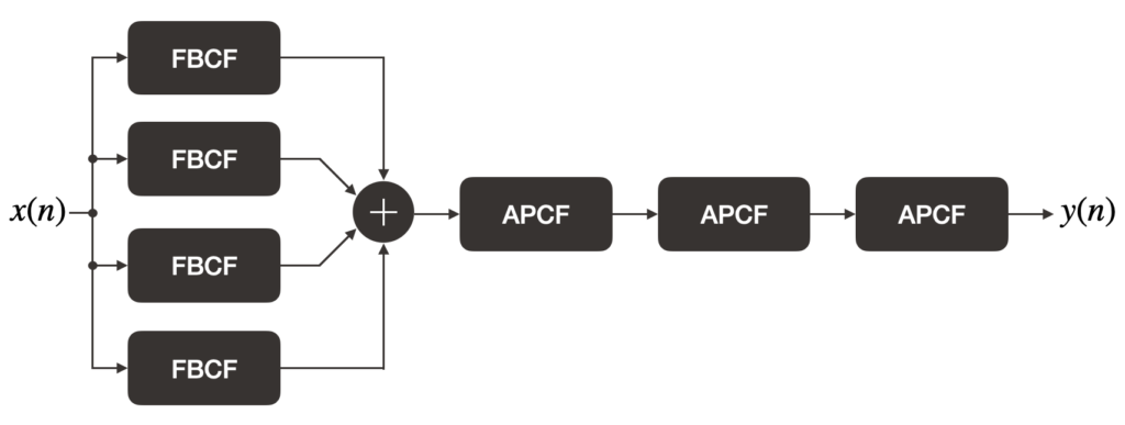
As we go over some of the different optimization techniques, we will apply them to the Schroeder reverberator and also measure the resulting performance gain (or hit). In Silly Audio Processing 8, we used the pre-made FBCF and APCF structures to build the reverberator. While this makes for more modular code, there is a performance hit due to overheads involved in the function calls for shifting in/out samples into the comb filters. For this post, we will “manually” create the comb filters within the Schroeder reverb struct:
typedef struct
{
    uint32_t    *fbDelayLineLengths;
    float32_t   *fbDelayLineA;
    float32_t   *fbDelayLineB;
    float32_t   *fbDelayLineC;
    float32_t   *fbDelayLineD;
    float32_t   *fbGains;

    uint32_t    *apDelayLineLengths;
    float32_t   *apDelayLineA;
    float32_t   *apDelayLineB;
    float32_t   *apDelayLineC;
    float32_t   apGain;

    int32_t     _fbDelayLineAPtr;
    int32_t     _fbDelayLineBPtr;
    int32_t     _fbDelayLineCPtr;
    int32_t     _fbDelayLineDPtr;

    int32_t     _apDelayLineAPtr;
    int32_t     _apDelayLineBPtr;
    int32_t     _apDelayLineCPtr;
}MW_AFXUnit_Schroeder;
The struct members fbDelayLine and apDelayLine contain pointers to arrays of floats that act as the comb filter’s delay lines. fbDelayLineLengths and apDelayLineLengths contains pointers to arrays that hold the length of each comb filter delay line. fbGains points to an array that holds the FBCF feedback gains while apGain is the feedback/feedforward gain of the APCFs. _fbDelayLinexPtr and _apDelayLinexPtr are indices that point to the next element in the delay line array where a sample should be read/written.
The initialization and process functions are below:
int32_t MW_AFXUnit_Schroeder_init(MW_AFXUnit_Schroeder *reverb)
{
    //  We need to check for a lot of things!
    //  nullptr checks
    if (reverb == NULL) return 0;
    if (reverb->fbDelayLineLengths == NULL ||
        reverb->fbDelayLineA == NULL ||
        reverb->fbDelayLineB == NULL ||
        reverb->fbDelayLineC == NULL ||
        reverb->fbDelayLineD == NULL ||
        reverb->fbGains == NULL)
        return 0;

    if (reverb->apDelayLineLengths == NULL ||
        reverb->apDelayLineA == NULL ||
        reverb->apDelayLineB == NULL ||
        reverb->apDelayLineC == NULL)
        return 0;

    for (int32_t i = 0; i < MW_AFXUNIT_SCHROEDER_NUM_FBCF; ++i)
    {
        if (reverb->fbDelayLineLengths[i] <= 0) return 0;
        if (reverb->fbGains[i] >= 1.f) return 0;
    }

    for (int32_t i = 0; i < MW_AFXUNIT_SCHROEDER_NUM_APCF; ++i)
        if (reverb->apDelayLineLengths[i] <= 0) return 0;

    if (reverb->apGain < 0 || reverb->apGain >= 1.f) return 0;

    reverb->_fbDelayLineAPtr = 0;
    reverb->_fbDelayLineBPtr = 0;
    reverb->_fbDelayLineCPtr = 0;
    reverb->_fbDelayLineDPtr = 0;

    reverb->_apDelayLineAPtr = 0;
    reverb->_apDelayLineBPtr = 0;
    reverb->_apDelayLineCPtr = 0;

    return 1;
}
void MW_AFXUnit_Schroeder_process(MW_AFXUnit_Schroeder *reverb, float32_t *buffer, const size_t bufferSize)
{
if (reverb == NULL) return;
for (int32_t i = 0; i < bufferSize; ++i)
{
// Feed the input signal through the FBCF bank
float32_t accumulator = 0.f;
float32_t x = buffer[i];
float32_t y_fb = (reverb->fbDelayLineA[reverb->_fbDelayLineAPtr] * reverb->fbGains[0]) + x;
reverb->fbDelayLineA[reverb->_fbDelayLineAPtr] = y_fb;
accumulator += y_fb;
y_fb = (reverb->fbDelayLineB[reverb->_fbDelayLineBPtr] * reverb->fbGains[1]) + x;
accumulator += y_fb;
reverb->fbDelayLineB[reverb->_fbDelayLineBPtr] = y_fb;
y_fb = (reverb->fbDelayLineC[reverb->_fbDelayLineCPtr] * reverb->fbGains[2]) + x;
accumulator += y_fb;
reverb->fbDelayLineC[reverb->_fbDelayLineCPtr] = y_fb;
y_fb = (reverb->fbDelayLineD[reverb->_fbDelayLineDPtr] * reverb->fbGains[3]) + x;
accumulator += y_fb;
reverb->fbDelayLineD[reverb->_fbDelayLineDPtr] = y_fb;
// Feed the accumulated signal through the APCF bank
float32_t b = reverb->apDelayLineA[reverb->_apDelayLineAPtr];
float32_t v = (b * -reverb->apGain) + accumulator;
reverb->apDelayLineA[reverb->_apDelayLineAPtr] = v;
float32_t y = b + (v * reverb->apGain);
b = reverb->apDelayLineB[reverb->_apDelayLineBPtr];
v = (b * -reverb->apGain) + y;
reverb->apDelayLineB[reverb->_apDelayLineBPtr] = v;
y = b + (v * reverb->apGain);
b = reverb->apDelayLineC[reverb->_apDelayLineCPtr];
v = (b * -reverb->apGain) + y;
reverb->apDelayLineC[reverb->_apDelayLineCPtr] = v;
// Put reverb output into buffer
buffer[i] = b + (v * reverb->apGain);
// Update delay line pointers
reverb->_fbDelayLineAPtr += 1;
if (reverb->_fbDelayLineAPtr >= reverb->fbDelayLineLengths[0])
reverb->_fbDelayLineAPtr = 0;
reverb->_fbDelayLineBPtr += 1;
if (reverb->_fbDelayLineBPtr >= reverb->fbDelayLineLengths[1])
reverb->_fbDelayLineBPtr = 0;
reverb->_fbDelayLineCPtr += 1;
if (reverb->_fbDelayLineCPtr >= reverb->fbDelayLineLengths[2])
reverb->_fbDelayLineCPtr = 0;
reverb->_fbDelayLineDPtr += 1;
if (reverb->_fbDelayLineDPtr >= reverb->fbDelayLineLengths[3])
reverb->_fbDelayLineDPtr = 0;
reverb->_apDelayLineAPtr += 1;
if (reverb->_apDelayLineAPtr >= reverb->apDelayLineLengths[0])
reverb->_apDelayLineAPtr = 0;
reverb->_apDelayLineBPtr += 1;
if (reverb->_apDelayLineBPtr >= reverb->apDelayLineLengths[1])
reverb->_apDelayLineBPtr = 0;
reverb->_apDelayLineCPtr += 1;
if (reverb->_apDelayLineCPtr >= reverb->apDelayLineLengths[2])
reverb->_apDelayLineCPtr = 0;
}
}The movement of samples into and out of the comb filters is all written in this function. The resulting processing time is below:
| No Optimization (-O0) | Optimization Level -O3 | |
| Module-based Code | 22 msec | 6 msec |
| This Code (New Baseline) | 13.54 msec | 3.94 msec |
The above times were measured by by toggling a GPIO pin high before MW_AFXUnit_Schroeder_process() was called and cleared on function exit. This pulse width was measured using a logic analyzer. The audio sampling frequency is 32 kHz with a buffer size of 1024 samples. The microcontroller used is the Silicon Labs EFM32PG12 clocked at 40 MHz.
Notice how enabling compiler optimizations resulted in a significant performance gain. We will have a brief discussion on compiler optimizations before moving onto other optimization methods.
Compiler Optimizations
Compilers are very good at optimizing code and simply setting our compiler optimization flags to -O1, 2, or 3 is often the first step in improving the performance of our code. The compiler uses a variety of techniques to optimize code such as function inlining, loop unrolling and (for more advanced processors) vectorizing. The GCC webpage on compiler optimizations gives a list of optimization techniques used.
There are a couple of main points to be aware of when working with compiler optimized code. First, since the compiler will likely reorganize your code, debugging can be difficult and you will find that as you step through code, the debugger will jump around to different lines of source code instead of sequentially. Second, depending on the optimization level, your executable may increase in size. This is worth checking as microcontrollers have very limited flash memory for code. Note that the -Os flag attempts to enable optimizations in -O2 while keeping the executable size low.
From the above table, we find that the compiler did a very good job of improving the execution time of our reverberator but can we do better?
Branches
If we look near the end of the reverb processing function, there is a block of code that increments the read/write indices of the comb filter delay lines. If the index is moved past the delay line size, it is reset back to zero. Instead of incrementing the index, what if we decremented instead?
int32_t MW_AFXUnit_Schroeder_init(MW_AFXUnit_Schroeder *reverb)
{
    //  ...

    //  Set the starting indices to the end of the delay line instead of the start
    reverb->_fbDelayLineAPtr = reverb->fbDelayLineLengths[0] - 1;
    reverb->_fbDelayLineBPtr = reverb->fbDelayLineLengths[1] - 1;
    reverb->_fbDelayLineCPtr = reverb->fbDelayLineLengths[2] - 1;
    reverb->_fbDelayLineDPtr = reverb->fbDelayLineLengths[3] - 1;

    reverb->_apDelayLineAPtr = reverb->apDelayLineLengths[0] - 1;
    reverb->_apDelayLineBPtr = reverb->apDelayLineLengths[0] - 1;
    reverb->_apDelayLineCPtr = reverb->apDelayLineLengths[0] - 1;

    return 1;
}
void MW_AFXUnit_Schroeder_process(MW_AFXUnit_Schroeder *reverb, float32_t *buffer, const size_t bufferSize)
{
// ...
// Update delay line pointers
reverb->_fbDelayLineAPtr -= 1;
if (reverb->_fbDelayLineAPtr < 0)
reverb->_fbDelayLineAPtr = reverb->fbDelayLineLengths[0] - 1;
reverb->_fbDelayLineBPtr -= 1;
if (reverb->_fbDelayLineBPtr < 0)
reverb->_fbDelayLineBPtr = reverb->fbDelayLineLengths[1] - 1;
reverb->_fbDelayLineCPtr -= 1;
if (reverb->_fbDelayLineCPtr < 0)
reverb->_fbDelayLineCPtr = reverb->fbDelayLineLengths[2] - 1;
reverb->_fbDelayLineDPtr -= 1;
if (reverb->_fbDelayLineDPtr < 0)
reverb->_fbDelayLineDPtr = reverb->fbDelayLineLengths[3] - 1;
reverb->_apDelayLineAPtr -= 1;
if (reverb->_apDelayLineAPtr < 0)
reverb->_apDelayLineAPtr = reverb->apDelayLineLengths[0] - 1;
reverb->_apDelayLineBPtr -= 1;
if (reverb->_apDelayLineBPtr < 0)
reverb->_apDelayLineBPtr = reverb->apDelayLineLengths[1] - 1;
reverb->_apDelayLineCPtr -= 1;
if (reverb->_apDelayLineCPtr < 0)
reverb->_apDelayLineCPtr = reverb->apDelayLineLengths[2] - 1;
}
}Measuring the execution time results in the following:
| No Optimization (-O0) | Optimization Level -O3 | |
| Baseline | 13.54 msec | 3.94 msec |
| Index Decrement | 12.17 msec | 3.74 msec |
Interestingly, this simple change made some difference! To understand why, let’s have a look at the disassembly:
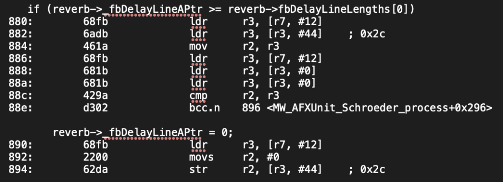
The above disassembly is from the baseline code (incrementing indices) without optimizations enabled (-O0). The if statement expands to several ldr instructions that load the delay line length (fbDelayLineLength) into register r3. From earlier instructions (not shown), r2 contains the delay line index (_fbDelayLineAPtr). The cmp instruction subtracts the contents of r3 from r2 (r2 – r3). If the result is 0 or positive, the program continues to the next set of instructions that reset _fbDelayLineAPtr to 0. However, if the result is negative, the program jumps to the instruction defined at 0x896 (this is where the index of the next delay line is incremented and compared). This if statement involves 8 instructions to execute.
Now, let’s have a look at the decrement disassembly:
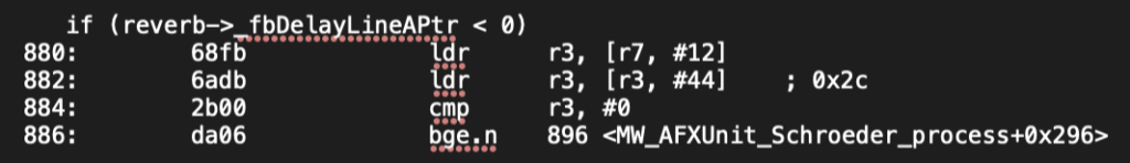
The number of instructions in the if statement is much smaller! Moreover, note that the cmp instruction compares the contents of r3 (_fbDelayLineAPtr) with the constant, 0 instead of the contents of some other register. This removes the need for extra ldr instructions observed in the above baseline code. Since there are fewer instructions to execute, the time taken to run the process function also decreases.
SIMD
SIMD (Single Instruction Multiple Data) is a form of parallelism that executes an instruction over more than 1 variable. For example suppose we have the following code that subtracts 1 and 2 from two variables:
int16_t a = 5;
int16_t b = 10;

int16_t c = a - 1;
int16_t d = b - 2;
When executing this code, the processor will first subtract 1 from a and then subtract 2 from b. There are a total of two subtraction operations. Instead of performing this operation twice, we can write SIMD code that subtracts 1 and 2 from a and b at the same time:
int16_t a = 5;
int16_t b = 10;
uint32_t packed = __PKHTB(a, b, 16);
uint32_t result = __SSUB16(packed, 0x00020001);

int16_t c = result & 0x0000FFFF;
int16_t d = result >> 16;
The variables a and b are packed into a single 32-bit variable, packed. The function __SSUB16 subtracts 1 and 2 from each variable in the package. Note that the constant 0x00020001 is 1 and 2 packed into a single uint32_t variable. To retrieve the individual results, some bit shifting and masking is needed.
We can use the above technique to speed up the index updating process:
typedef struct
{
uint32_t *fbDelayLineLengths;
float32_t *fbDelayLineA;
float32_t *fbDelayLineB;
float32_t *fbDelayLineC;
float32_t *fbDelayLineD;
float32_t *fbGains;
uint32_t *apDelayLineLengths;
float32_t *apDelayLineA;
float32_t *apDelayLineB;
float32_t *apDelayLineC;
float32_t apGain;
uint32_t _fbPtrPackedA;
uint32_t _fbPtrPackedB;
uint32_t _apPtrPackedA;
uint32_t _apPtrPackedB;
uint32_t _fbDelayLengthPackedA;
uint32_t _fbDelayLengthPackedB;
uint32_t _apDelayLengthPackedA;
uint32_t _apDelayLengthPackedB;
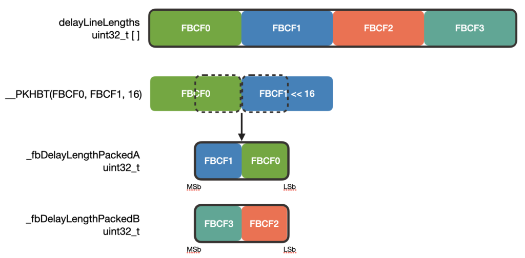
}MW_AFXUnit_Schroeder;_fbPtrPackedx and _apPtrPackedx pack 2 delay line indices into a single uint32_t member. Note that packing two variables into a single uint32_t variable results in the individual index type changing from int32_t to int16_t. Be careful that the delay line length does not exceed 32767!
We have also defined members _fbDelayLengthPackedx and _apDelayLengthPackedx. These are constants that package the delay line lengths into a single uint32_t variable. We will soon see why they are important.
int32_t MW_AFXUnit_Schroeder_init(MW_AFXUnit_Schroeder *reverb)
{
    //  Initial checks...

    //  Pack delay line lengths into uint32_t variables
    reverb->_fbDelayLengthPackedA = __PKHBT(reverb->fbDelayLineLengths[0] - 1, reverb->fbDelayLineLengths[1] - 1, 16);
    reverb->_fbDelayLengthPackedB = __PKHBT(reverb->fbDelayLineLengths[2] - 1, reverb->fbDelayLineLengths[3] - 1, 16);
    reverb->_apDelayLengthPackedA = __PKHBT(reverb->apDelayLineLengths[0] - 1, reverb->apDelayLineLengths[1] - 1, 16);
    reverb->_apDelayLengthPackedB = __PKHBT(reverb->apDelayLineLengths[2] - 1, 0, 0);

    reverb->_fbPtrPackedA = reverb->_fbDelayLengthPackedA;
    reverb->_fbPtrPackedB = reverb->_fbDelayLengthPackedB;
    reverb->_apPtrPackedA = reverb->_apDelayLengthPackedA;
    reverb->_apPtrPackedB = reverb->_apDelayLengthPackedB;

    return 1;
}
In the initialization, starting indices and delay line lengths are packed into their respective struct members. While you can use bit-shifting and ORing to do the packing, the ARM offers a convenient function, __PKHBT() to do this for us. __PKHBT takes two words (32-bits), val1 and val2 and a third input, val3. The return value is a word-length variable with the lower half-word (16-bits) of val1 and the upper half-word of val2 shifted left by val3 bits:
The process function is as follows:
void MW_AFXUnit_Schroeder_process(MW_AFXUnit_Schroeder *reverb, float32_t *buffer, const size_t bufferSize)
{
#ifdef NO_OPTIMIZE
if (reverb == NULL) while(1);
#else
if (reverb == NULL) return;
#endif
for (int32_t i = 0; i < bufferSize; ++i)
{
// Feed the input signal through the FBCF bank
float32_t accumulator = 0.f;
float32_t x = buffer[i];
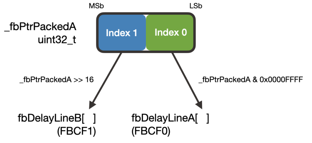
uint32_t delayLineIndex = reverb->_fbPtrPackedA & 0x0000FFFF;
float32_t y_fb = (reverb->fbDelayLineA[delayLineIndex] * reverb->fbGains[0]) + x;
reverb->fbDelayLineA[delayLineIndex] = y_fb;
accumulator += y_fb;
delayLineIndex = reverb->_fbPtrPackedA >> 16;
y_fb = (reverb->fbDelayLineB[delayLineIndex] * reverb->fbGains[1]) + x;
accumulator += y_fb;
reverb->fbDelayLineB[delayLineIndex] = y_fb;
delayLineIndex = reverb->_fbPtrPackedB & 0x0000FFFF;
y_fb = (reverb->fbDelayLineC[delayLineIndex] * reverb->fbGains[2]) + x;
reverb->fbDelayLineC[delayLineIndex] = y_fb;
accumulator += y_fb;
delayLineIndex = reverb->_fbPtrPackedB >> 16;
y_fb = (reverb->fbDelayLineD[delayLineIndex] * reverb->fbGains[3]) + x;
accumulator += y_fb;
reverb->fbDelayLineD[delayLineIndex] = y_fb;
// Feed FBCF output into APCF filters
delayLineIndex = reverb->_apPtrPackedA & 0x0000FFFF;
float32_t b = reverb->apDelayLineA[delayLineIndex];
float32_t v = (b * -reverb->apGain) + accumulator;
reverb->apDelayLineA[delayLineIndex] = v;
float32_t y = b + (v * reverb->apGain);
delayLineIndex = reverb->_apPtrPackedA >> 16;
b = reverb->apDelayLineB[delayLineIndex];
v = (b * -reverb->apGain) + y;
reverb->apDelayLineB[delayLineIndex] = v;
y = b + (v * reverb->apGain);
delayLineIndex = reverb->_apPtrPackedB & 0x0000FFFF;
b = reverb->apDelayLineC[delayLineIndex];
v = (b * -reverb->apGain) + y;
reverb->apDelayLineC[delayLineIndex] = v;
// Put reverb output into buffer
buffer[i] = b + (v * reverb->apGain);
// Update delay line indices
reverb->_fbPtrPackedA = __SSUB16(reverb->_fbPtrPackedA, 0x00010001);
reverb->_fbPtrPackedA = __SEL(reverb->_fbPtrPackedA, reverb->_fbDelayLengthPackedA);
reverb->_fbPtrPackedB = __SSUB16(reverb->_fbPtrPackedB, 0x00010001);
reverb->_fbPtrPackedB = __SEL(reverb->_fbPtrPackedB, reverb->_fbDelayLengthPackedB);
reverb->_apPtrPackedA = __SSUB16(reverb->_apPtrPackedA, 0x00010001);
reverb->_apPtrPackedA = __SEL(reverb->_apPtrPackedA, reverb->_apDelayLengthPackedA);
reverb->_apPtrPackedB = __SSUB16(reverb->_apPtrPackedB, 0x00000001);
reverb->_apPtrPackedB = __SEL(reverb->_apPtrPackedB, reverb->_apDelayLengthPackedB);
}
}There is a lot to unpack here! Calculating the filter outputs is largely unchanged. The main difference is in how the delay line sample is read. Since the delay line indices are packed into a single word, we need to extract the proper index (half-word) for its respective delay line by using masks and bit shifting:
To subtract 1 from each delay line index, we use the __SSUB16() function. Remember that to subtract 1 from each of the packed delay line indices, we pass in the constant 0x00010001 (2 half-word 1’s packed into a word) to __SSUB16:
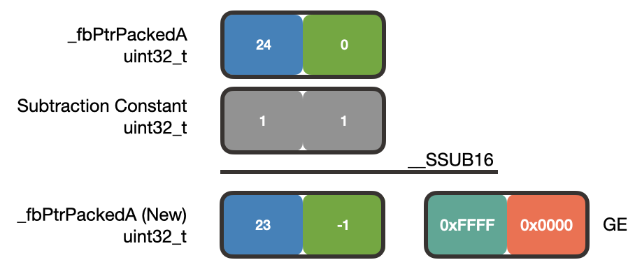
In this example, _fbPtrPackedA is packed with the index values 24 and 0. Subtracting 1 from each index results in 23 and -1. Additionally, __SSUB16() will modify the GE (Greater than or Equal) register depending on the sign of the result. Since the upper half-word of the result is positive, the upper half-word of GE is set to 0xFFFF. The lower half-word of the result is negative so the lower half-word of GE is cleared to 0x0000.
To reset the negative index value, we use the __SEL function which will examine the contents of GE to make decisions about the returned value:
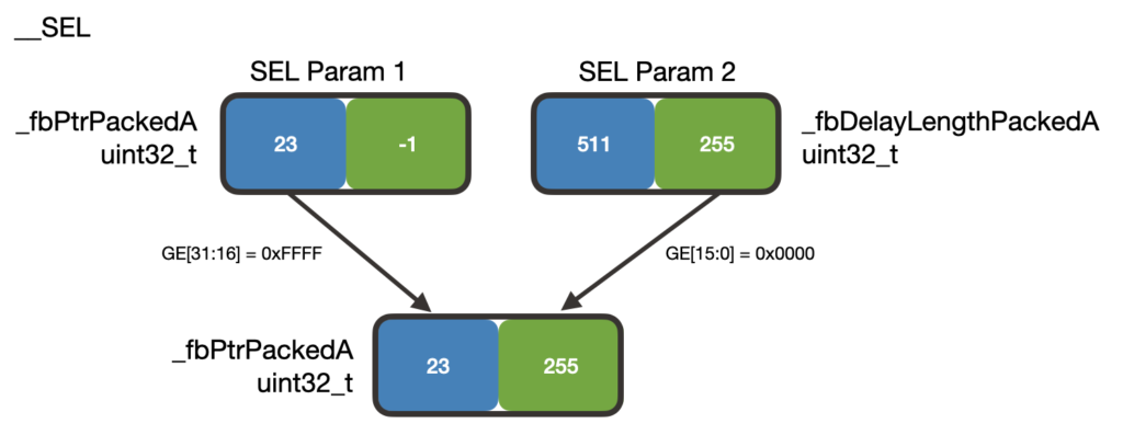
The inputs to the __SEL function are _fbPtrPackedA and _fbDelayLengthPackedA (the lengths of the first two FBCF delay lines). In this example, the delay lengths are 511 and 255 samples long. The __SEL function sees that the upper half-word of GE is 0xFFFF and places the upper half-word of _fbPtrPackedA into the upper half-word of the result.
The lower half-word of GE is 0x0000 so __SEL takes the lower half-word of _fbDelayLengthPackedA and places it into the lower half-word of the result. _fbPtrPackedA now has the correct index values.
The following table shows the performance gains:
| No Optimization (-O0) | Optimization Level -O3 | |
| Baseline | 13.54 msec | 3.94 msec |
| Index Decrement | 12.53 msec | 3.74 msec |
| Index Decrement SIMD | 13.7 msec | 2.86 msec |
With optimizations enabled, using SIMD to update indices shaves off 0.88 msec. A significant performance gain! The increased time with no optimization enabled is possibly due to the extra data load instructions in preparation for the SIMD instructions.
Floating Point vs Fixed Point Numbers
While we used SIMD to speed up index updates, you may wonder if similar techniques can be applied to calculating the reverb output. The answer is…it depends. SIMD registers for the ARM Cortex M4 family are 32-bits long. Since floating point numbers are also 32-bits long, only 1 value can fit into the register so we cannot parallelize the reverb calculations. However, we can still use SIMD for the calculations if we use fixed point numbers. We may cover this in a different post.
This section gave a brief introduction to SIMD for the ARM Cortex M4 processor. Those familiar with SIMD in modern x86 processors may find the 32-bit register length limiting but there is still quite a lot that we can do with 32-bits. There are many more SIMD intrinsic functions that were not covered here. I encourage you to have a look at them.
Some final notes about using SIMD. First, they do not guarantee better performance! It is very possible that an algorithm implemented with SIMD (vectorized code) is still slower than the algorithm implemented without using SIMD (scalar code). Therefore, using SIMD in the beginning stages of algorithm implementation is not advised.
Second, when parallelizing algorithms, the resulting SIMD code can be notoriously difficult to read. This is something you should consider when weighing the tradeoffs between readable and fast code.
Finally, there are some memory alignment considerations to make when using SIMD in certain situations. The intricacies of SIMD are out of scope for this post but may appear in a future post.
Other Things
There are some ways of writing code that may seem insignificant but have interestingly significant impact on the resulting performance of your code. We will look at two such instances.
First, notice how in the calculation of the FBCF bank output, we created a variable x that holds a buffer sample and then used x to calculate each FBCF’s outputs. What if we had written buffer[i] instead?
//  FBCF Calculation
float32_t y_fb = (reverb->fbDelayLineA[reverb->_fbDelayLineAPtr] * reverb->fbGains[0]) + buffer[i];
reverb->fbDelayLineA[reverb->_fbDelayLineAPtr] = y_fb;
accumulator += y_fb;

//  ...
Using the index decrement SIMD code from before and measuring the performance yields the following numbers:
| No Optimization (-O0) | Optimization Level -O3 | |
| Index Decrement SIMD Using local variable x | 13.7 msec | 2.86 msec |
| Index Decrement SIMD Not using local variable x | 14.36 msec | 2.96 msec |
Comparing the times with optimization enabled, the 0.1 msec is a marginal gain but could mean the difference between meeting the timing budget or not. Let’s have a look at the disassembly:
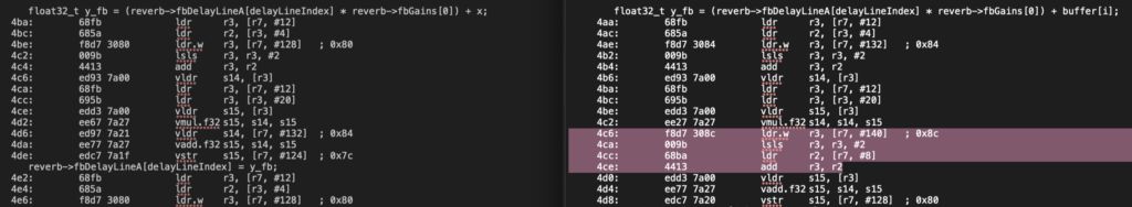
The code on the right calculates the FBCF output using buffer[i]. Notice how the compiler adds instructions that first retrieves the loop variable, i, then adds that to the address of the start of buffer, then retrieves the contents from the resulting address and loads it into a floating point register via vldr. In the faster example (left), this calculation of the address of buffer[i] only occurs once and the sample is stored in stack memory (where it lives in the address stored in r7 plus an offset of 132). x is then retrieved from stack memory via the vldr instruction. This is much faster than locating the input sample using the previous method (through buffer[i]).
The second small optimization trick is splitting up loops. The reverb output calculation is in one loop. What if we separated the the FBCF output calculations and APCF output calculations into two separate loops?
void MW_AFXUnit_Schroeder_process(MW_AFXUnit_Schroeder *reverb, float32_t *buffer, const size_t bufferSize)
{
  for (int32_t i = 0; i < bufferSize, ++i)
  {
    //  FBCF Output Calculations
    buffer[i] = FBCF_Output
  }

  for (int32_t i = 0; i < bufferSize, ++i)
  {
    //  APCF (Reverb) Output Calculations
    buffer[i] = APCF_Output
  }
}
Again, using SIMD to update the delay line indices, here is the difference in performance:
| No Optimization (-O0) | Optimization Level -O3 | |
| Index Decrement SIMD Single for-loop | 13.7 msec | 2.86 msec |
| Index Decrement SIMD Split for-loop | 14.15 msec | 2.57 msec |
The nearly 0.3 msec difference (-O3) is fairly significant! The exact mechanics that the compiler uses to optimize this code is unclear but it is possible that by splitting up the FBCF and APCF sections, the compiler was able to find more optimization opportunities that it otherwise would not have with just a single for-loop. This isn’t guaranteed to work for all algorithms which is why it is important to profile your code!
CMSIS DSP Libraries
ARM has created a library of fast DSP functions as part of its CMSIS libraries (targeted for the ARM Cortex microcontrollers). Some of the functions include basic math functions such as adding elements from two arrays together, fast trigonometric functions, linear algebra operations and even filtering functions. These are all operations that are frequently used in DSP code and using the accelerated versions of these operations will help boost your performance.
Speaking of DSP, the Music DSP website is an amazing collection of audio effect implementations that are also often optimized. It is a great place to have a look around.
A Quick Note About Assembly Language
In some sections, we examined the code disassembly to understand why certain code ran faster. While knowing assembly language is by no means a prerequisite to writing fast code, it is often helpful to have an understanding of it when digging deeper into the optimization world. It is not a terribly difficult language to learn and there are many learning resources online.
Conclusions
Let’s summarize the performance gains in one table:
| No Optimization (-O0) | Optimization Level -O3 | |
| Baseline | 13.54 msec | 3.94 msec |
| Index Decrement | 12.53 msec | 3.74 msec |
| Index Decrement SIMD | 13.7 msec | 2.86 msec |
| Index Decrement SIMD Split for-loop | 14.15 msec | 2.57 msec |
We were able to shave about 1.37 msec from our baseline code – a nearly 35% performance gain. It’s important to understand that the significance of these numbers depends on context. If the budgeted audio processing time was 32 msec and reverb was the only effect being used, then the optimization efforts were probably not needed. If the budget was 4 msec however, then the optimization efforts certainly paid off!
This was a lot of information to absorb! And we haven’t even scratched the surface of optimization techniques! There are a lot of articles on the internet and recorded conference talks that go into more optimization tricks. If this is your field of interest then I highly encourage you to check them out.