
Comb Filters
The previous post introduced the delay line which, by itself doesn’t create particularly interesting sounds. However, it is one of the fundamental building blocks for many (interesting) audio effects.
In this post, we will be using the delay line to create another family of basic building blocks also often used to create audio effects, the comb filter.
Comb filters, so called due their frequency magnitude response looking like the teeth of a comb, are particularly useful for modelling echos – which lends itself well to creating reverb effects (which we will be exploring in the next post).
The three types of comb filters that we will go over in this post are the feed-forward, feedback and all-pass comb filters. We will go through a brief introduction to the filter topologies and their implementation. References to more in-depth analyses are provided at the end of the post should you wish to dive deeper into the subject.
Feed-Forward Comb Filters
The Feed-Forward Comb Filter (FFCF) is easy to understand and implement. At its simplest, it consists of a single delay line whose output is added with its input:
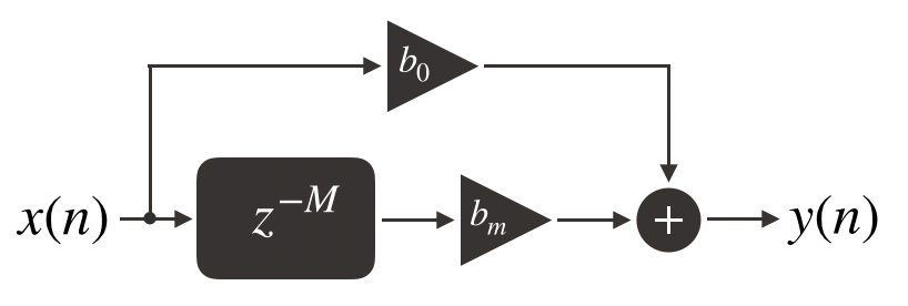
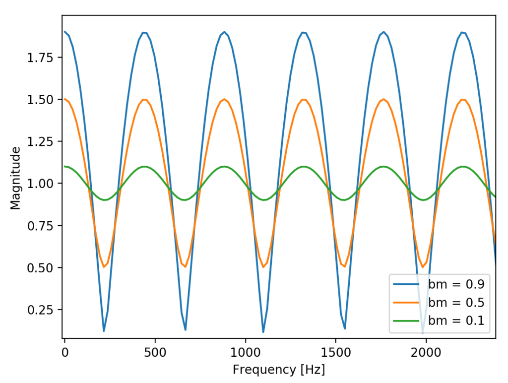
A couple of key things to note here are that both the delay line output and input (x(n)) are scaled by bm and b0 respectively. Changing bm tends to change the amplitude of the cosine-like curve of the magnitude spectrum while changing b0 shifts the curve up or down.
Implementation
The C code below creates a framework for the FFCF:
typedef struct
{
  float32_t b0;
  float32_t bm;
  DelayLine *M;
}FFCF;
Since the FFCF needs a delay line, we leverage our previous DelayLine implementation and include it in the FFCF struct.
Creating a FFCF instance is done as follows;
FFCF *createFFCF(size_t M, float32_t b0, float32_t bm)
{
  FFCF *f = (FFCF *)malloc(sizeof(FFCF));
  if (f == NULL)
    return NULL;

  f->M = createDelayLine(M);
  if (f->M == NULL)
  {
    free(f);
    return NULL;
  }

  f->b0 = b0;
  f->bm = bm;

  return f;
}
Creating an FFCF is similar to creating a delay line. Memory is allocated for the FFCF instance, an instance of the delay line is created, FFCF gain parameters bm and b0 are set and a pointer to the FFCF instance is returned.
To execute a cycle of FFCF operation, we first need to input a sample into the delay line and get a sample from it. This can be done via the delayLineShift function. Once a sample from the delay line is obtained, we scale the delay line output with bm, scale the input with b0 and add them together to get the filter output.
int ffcfShift(FFCF *f, float32_t x, float32_t *y)
{
  if (f == NULL) return -1;

  //  Shift data into the delay line and get a sample from it
  float d_y = 0;
  int status = delayLineShift(f->M, x, &d_y);

  if (status < 0)
    return -1;

  //  Calculate the FFCF output using the input and delay line output
  *y = (x * f->b0) + (d_y * f->bm);

  return 0;
}
How it Sounds
The following audio clips are used to observe the changes that the FFCF (and subsequent filters) make. The first sample is a sine sweep and the other is a clip of a song.
Sine Sweep
Applying a FFCF filter with M=100, b0=1.0 and bm=0.9 creates a similar sweep sound as the original but with some frequencies going in and out of volume, consistent with the frequency spectrum characteristic of a FFCF shown earlier:
Song Clip
Applying a FFCF filter with M=100, b0=1.0 and bm=0.9 causes the audio to take on a “hollow” characteristic. Increasing the delay length, M to 3000 yields audio that sounds almost reverberant while further increasing the delay length to 10000 creates very noticeable echos.
Feedback Comb Filters
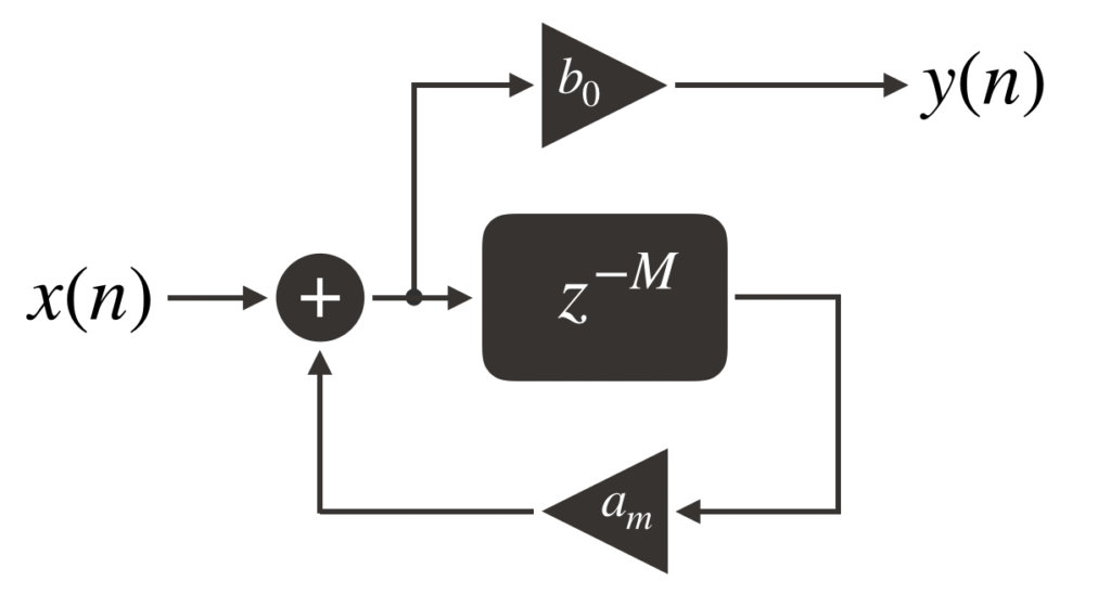
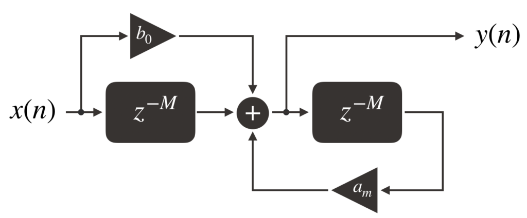
Like the FFCF, the feedback comb filter (FBCF) makes use of a delay line. While the FFCF forwards the input sample to the output, the FBCF feeds the output of its delay line back towards its input. The input of the delay line is a summation of the filter input and the scaled delay line output. The filter output is a scaled version of the delay line input.

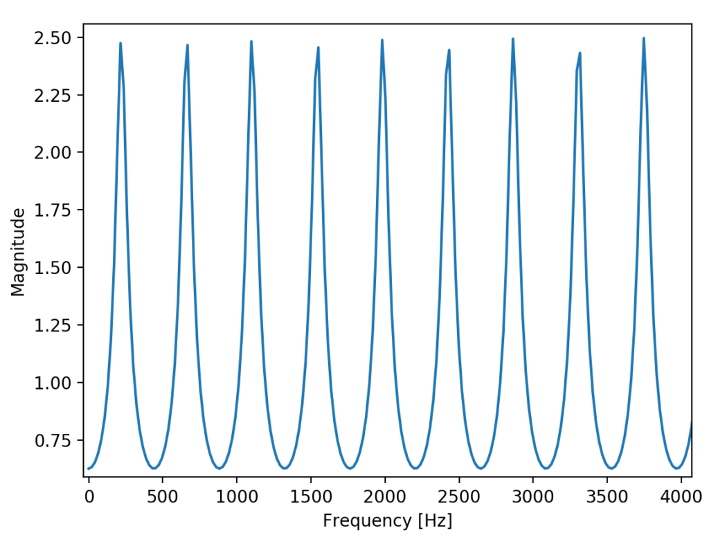
The spectral characteristic of a FBCF is also comb-shaped but while the FFCF has peaks that gradually turn into valleys, the FBCF has sharper peaks that rapidly turn into valleys. Changing am will change how sharp the peaks will be.
To prevent the FBCF from oscillating or outputting deafening noises (or both), am must be less than 1. This constraint keeps the filter stable.
Implementation
Similar to the FFCF, the FBCF struct contains a delay line and gain parameters:
typedef struct
{
  float32_t b0;
  float32_t am;
  DelayLine *M;
}FBCF;
Creating a FBCF instance is also similar:
FBCF *createFBCF(size_t M, float32_t b0, float32_t am)
{
  FBCF *f = (FBCF *)malloc(sizeof(FBCF));
  if (f == NULL)
    return NULL;

  f->M = createDelayLine(M);
  if (f->M == NULL)
  {
    free(f);
    return NULL;
  }

  f->b0 = b0;
  f->am = am;

  return f;
}
To calculate the delay line input, we need information about the delay line’s output. To do this, the delayLinePeek function is used to “peek” at what the delay line’s next output will be without having to shift in an input value (as is required by the delayLineShift function).
int fbcfShift(FBCF *f, float32_t x, float32_t *y)
{
  if (f == NULL) return -1;

  //  Peek at the delay line output to get the value needed to calculate the delay line input value
  float32_t delayOut = 0;
  delayLinePeek(f->M, &delayOut);

  //  Calculate the delay line input value
  //  delayOut is passed into delayLineShift() simply as a placeholder
  //  as the function needs to have some variable passed in to work properly
  float32_t v = (delayOut * f->am) + x;
  int status = delayLineShift(f->M, v, &delayOut);

  if (status < 0)
    return -1;

  //  Calculate the filter output value
  *y = v * f->b0;

  return 0;
}
How it Sounds
Sine Sweep
Applying a FBCF filter to a sine sweep results in audio that is consistent with the FBCF spectrum from earlier. Since the peaks go up and down quicker than the FFCF, the volume for some frequencies also go up and down quickly:
Song Clip
With M=100, the resulting sound is as if you were listening to the original audio but through a seashell or cup that you hold up to your ear. At M=4000, the sound is slightly reverberant and somewhat similar to the sound of a spring reverberator found in many guitar amps:
Allpass Comb Filters
An allpass filter passes all frequencies. However, they introduce delays in the phase of different frequencies. The allpass comb filter (APCF) is created by connecting a FFCF and FBCF in series:
It is possible however to create an APCF using only one delay line element instead of two. In this case, we would only need to call delayLineShift on one delay line instead of two so the number of computations is reduced. The disadvantage of this topology is that when using fixed point representation (as opposed to floating point), there is the risk of overflow.
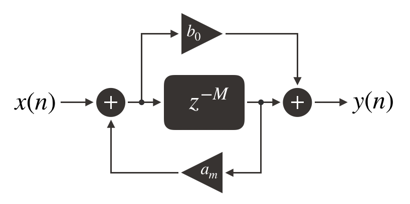
The first APCF topology is known as Direct Form I while the second is known as Direct Form II. In this post, we will implement the Direct Form I APCF.
Implementation
Below is the struct for the APCF. It leverages the FFCF and FBCF implementations that we built earlier to create the foundation:
typedef struct
{
  FFCF *ff;
  FBCF *fb;
}APCF;
One thing to note is that there are no gain parameters explicitly declared on this struct. This is because the gain parameters of the APCF are actually part of its FFCF and FBCF constituents. The gain parameters are set when creating an APCF instance:
APCF *createAPCF(size_t M, float32_t b0, float32_t am)
{
  APCF *a = (APCF *)malloc(sizeof(APCF));
  if (a == NULL)
    return NULL;

  a->ff = createFFCF(M, b0, 1);
  if (a->ff == NULL)
  {
    free(a);
    return NULL;
  }

  a->fb = createFBCF(M, 1, am);
  if (a->fb == NULL)
  {
    free(a);
    return NULL;
  }

  return a;
}
During the creation process, bm in the FFCF and b0 in the FBCF are set to 1. Generally in the context of APCFs, am and b0 are negative versions of themselves, i.e. am = -b0.
Operating the APCF involves calculating the output from the FFCF section first and then using that value as the input into the FBCF. The output of the FBCF is the output of the APCF.
int apcfShift(APCF *a, float32_t x, float32_t *y)
{
  if (a == NULL) return -1;

  //  Calculate the output of the FFCF first
  float32_t d_y = 0;
  int status = ffcfShift(a->ff, x, &d_y);
  if (status < 0)
    return -1;

  //  Use the output of the FFCF as input into the FBCF and calculate the output of the FBCF
  status = fbcfShift(a->fb, d_y, &d_y);
  if (status < 0)
    return -1;

  *y = d_y;

  return 0;
}
How it Sounds
Sine Sweep
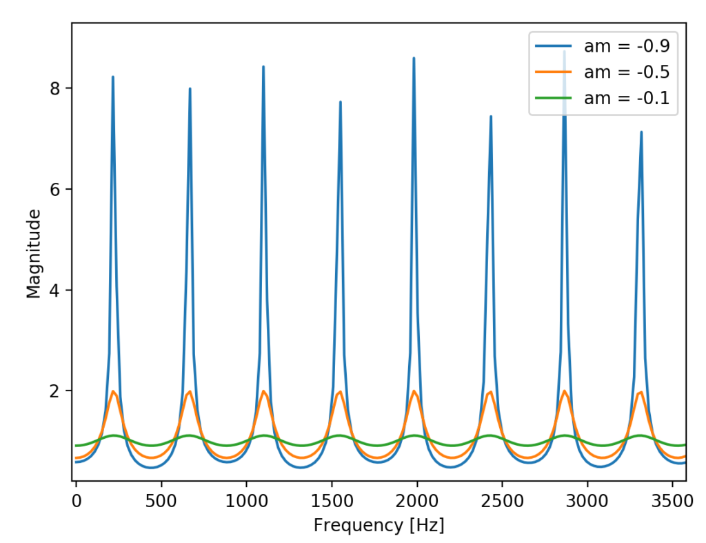
As its name suggests, the APCF should not affect the volume of the sine sweep. However in practice and in certain cases, the APCF magnitude spectrum may not be completely flat depending on your choice of gain and delay length so it may be possible to hear slight changes in volume as the frequency increases:
Sound Clip
While the APCF’s flat frequency magnitude response doesn’t appear to suggest anything interesting sonically, when the delay length is increased it’s usefulness as an echo generator is quickly apparent:
Putting it all Together
An example project making use of the comb filters and delay line is available on Github. Like the delay line, the comb filters undergo a cycle of creation, operation and deletion throughout the program lifetime.
// main.c

#include "DelayLine.h"

#define NUM_BUFFERS 4
#define BUFFER_SIZE 256
#define QUEUE_SIZE (NUM_BUFFERS)

//  All the peripheral initializations, defines, interrupts, and necessary variables are omitted here.
//  Refer to SAP 4 for this part of the code OR the examples in Github

int main(void)
{
  // ...

  //  Create delay lines and comb filters here
  const size_t delayLength = 2000;

  DelayLine *d = createDelayLine(delayLength);
  FFCF *ff = createFFCF(delayLength, 1.f, 0.8f);
  FBCF *fb = createFBCF(delayLength, 1.f, -0.8f);
  APCF *ap = createAPCF(delayLength, 0.8f, -0.8f);


  while(1)
  {
    //  Check to make sure there is a buffer available for processing
    if (processingQueue[processingQueueHead] != NULL)
    {
      //  Fancy processing code here
      //  Apply delay lines or comb filters.  To observe the effects of the delay line or comb filter, comment out ffcfShift()
      //  and uncomment the filter / delay line that you want to use.  Only one shift function should be uncommented at a time.
      for (int i = 0; i < BUFFER_SIZE; ++i)
      {
        float32_t y = 0.0f;

        //delayLineShift(d, processingQueue[processingQueueHead][i], &y);
        ffcfShift(ff, processingQueue[processingQueueHead][i], &y);
        //fbcfShift(fb, processingQueue[processingQueueHead][i], &y);
        //apcfShift(ap, processingQueue[processingQueueHead][i], &y);

        processingQueue[processingQueueHead][i] = y;
      }

      transferBufferToQueue(processingQueue[processingQueueHead], dacQueue, &dacQueueTail);

      processingQueue[processingQueueHead] = NULL;
      processingQueueHead = (processingQueueHead + 1) % QUEUE_SIZE;
    }
  }

  //  Remember to release any memory that you've allocated!
  deleteDelayLine(d);
  deleteFFCF(ff);
  deleteFBCF(fb);
  deleteAPCF(ap);
}
Resources
For those looking for a more in-depth discussion of comb filters, the following CCRMA resources are a great place to start: