
For the next few posts, we will be going into the nitty gritty details of the conditioning circuit. I want to spend lots of time at this stage for two reasons:
- Analog circuits and analysis have never been my strong points and this is a great way to change that
- The last thing we want, is to work with erroneous data caused by poor design of the conditioning circuit
Today, we will be briefly looking at the circuit and focusing on its behaviour.
As mentioned in previous posts, the geophone used for this project is the SM-24 model from SENSOR. Since I’ve never designed a circuit for this particular application, I began looking for a reference design to work off of. I even went as far as emailing SENSOR product support (to no avail) for any literature that might be useful.
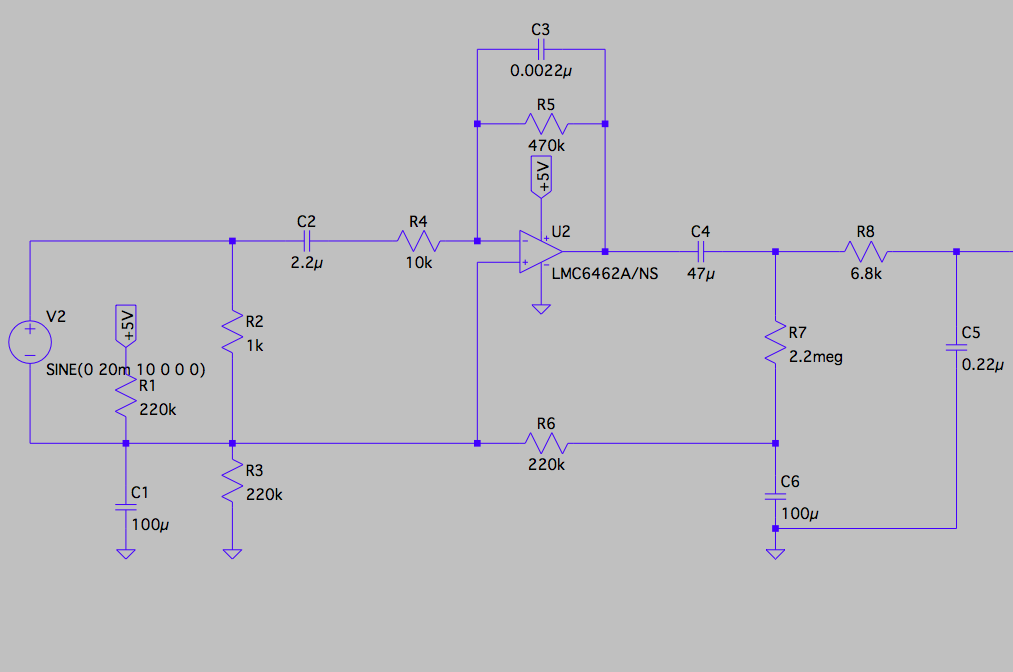
I was able to find an example circuit (its demo can be found here) in the comment section on Sparkfun’s product page. Overall, the circuit seems pretty well-fit for the job. It makes use of the TI LMC6462s which are (really) low power op amps, perfect for us since we plan to use solar power. It also features a pretty good offset voltage (0.25 mV) and slew rate (15 V/ms). At most, our application needs a SR of about 4 V/ms so we are well within spec.
Speaking of specs, what do we want, exactly??
For now, there are two big things. First, our signals will most likely be weak so we need a gain. Actually we need a lot of gain. Cue a response to one of my questions on Stackexchange:
What do you want to measure? I can expand in an answer. Geophone frequency response is not good for detecting distant earthquakes and are designed to detect vertical motion – also not so good. If you are going to pound on the ground with a sledge hammer or shotgun slugs and get echos from rock layers, OK. For natural seismic activity you will need gain of a million or so. You can do it with two opamps of gain 1000 each and low pass filtered (cap across the feedback resistor). If you want earthquakes, build a simple seismometer with a period of at least a second.
Okay, let’s shelf detecting natural seismic activity for now and pick a gain of 1000. Luckily our reference design already has a gain of 1000 (50 x 20 from the two opamp stages).
The other big thing we are concerned about is what kind of frequency response do we want? A quick look at the SM-24 datasheet can give us a hint:
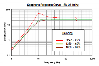
Courtesy of SENSOR
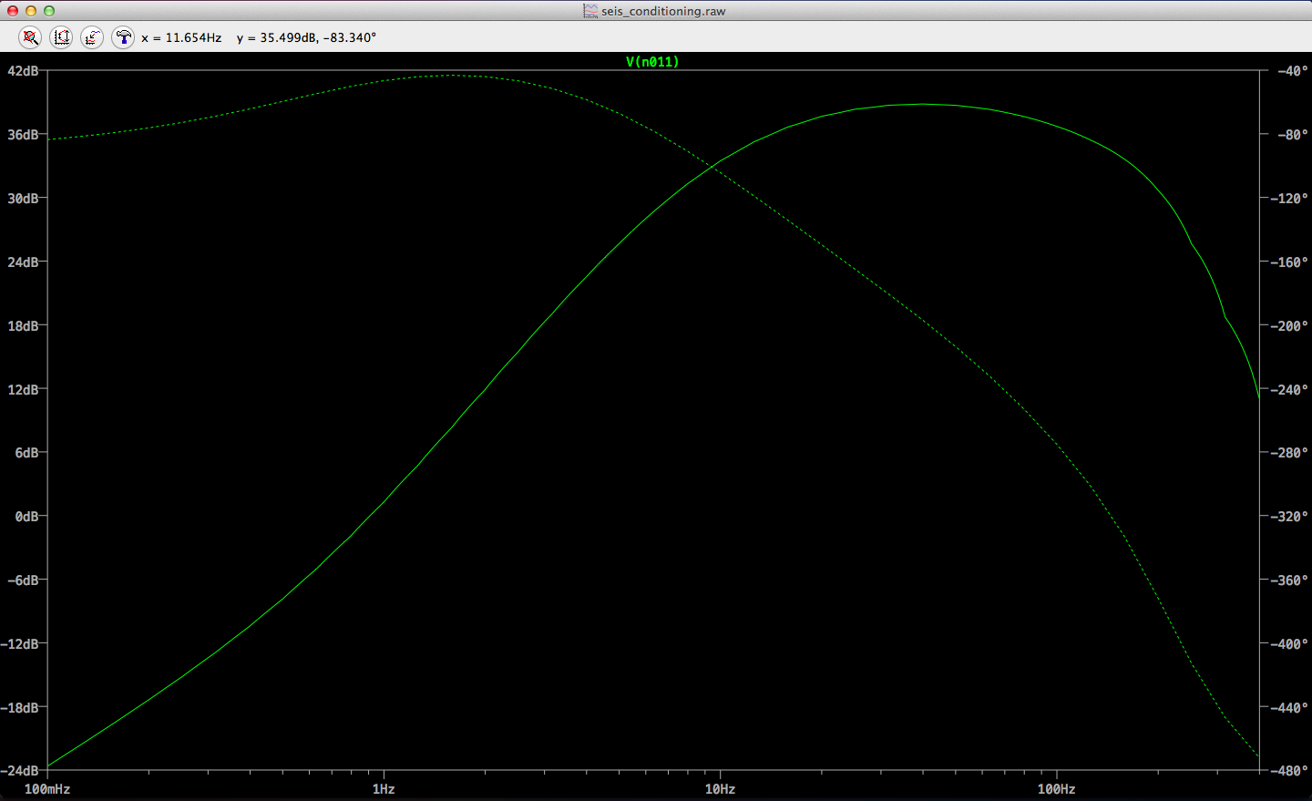
So with the spec on hand (actually, on the second thought, they’re not really specs since we’re just playing with the circuit. We’re more so trying to give ourselves really loose guidelines), let’s take a look at our reference circuit. To start, I brought back a ghost from college to help me: LTSpice – perhaps the bane of many EE students at the time, myself included. A frequency sweep from 1 to 400 Hz shows the following response:
I don’t have a function generator handy but because we are dealing with low frequencies, I could use my computer as a function generator! Using a neat program called Baudline I was able to do a frequency sweep using its tone generator feeding in a 20 mVpp sinusoid to our circuit.
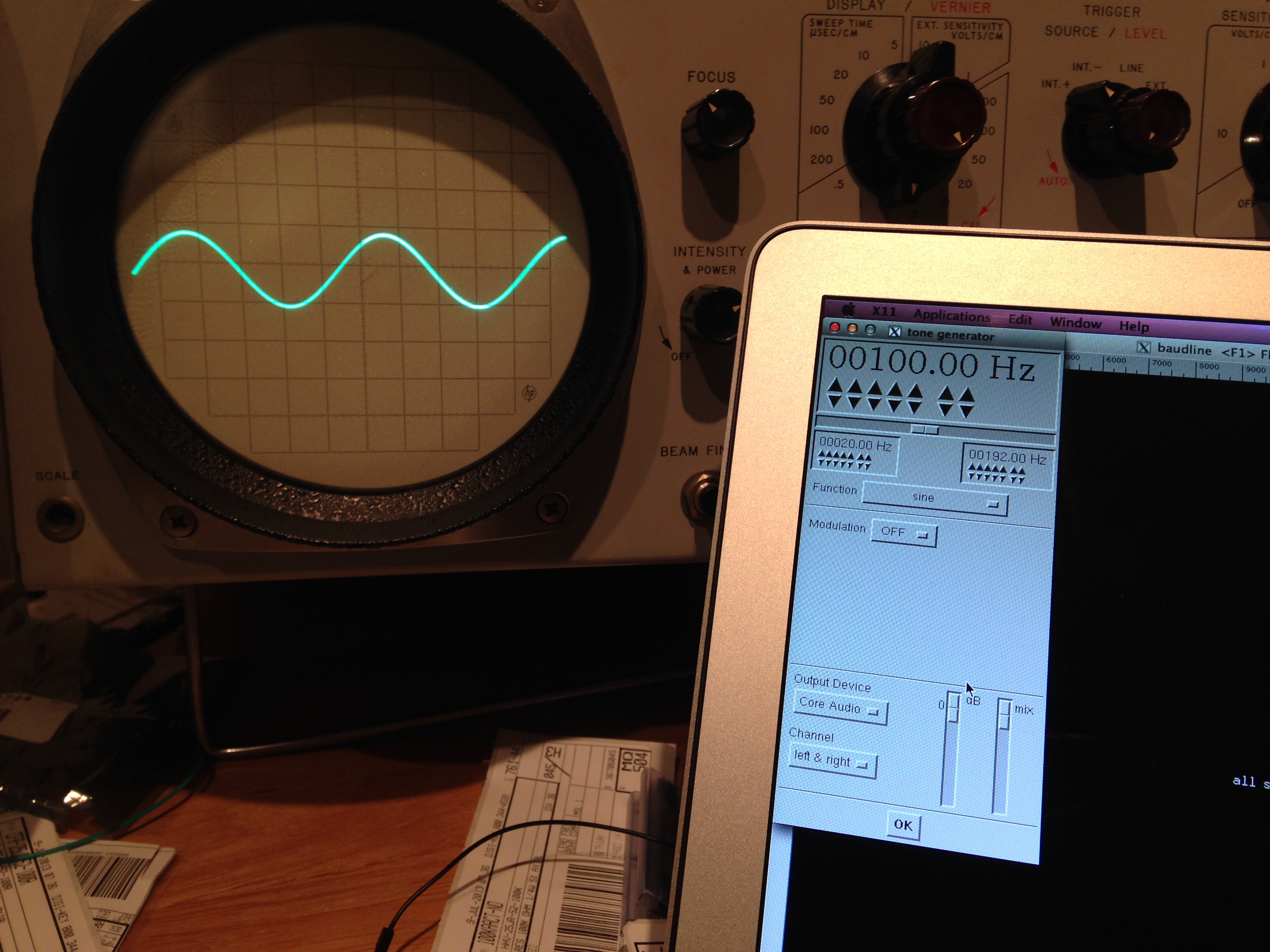
After a whole lot of measuring, we finally have real world results to compare our simulation against:
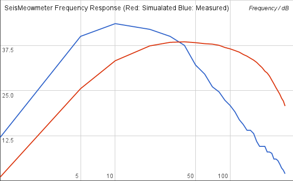
Interestingly, the top gain of the actual circuit (in blue) is some magnitudes higher than the simulation (in red)! Unfortunately, we don’t quite hit our desired gain of 1000 V/V or 20log(1000) = 60 dB. Another problem is that both circuits don’t have a flat(ish) frequency response past 100. Actually, the real circuit is worse, having a cutoff frequency of about 40 Hz! The simulated 100 Hz cutoff was actually expected because of the RC resistor network after the first opamp stage. fc at 6.8kΩ/0.22uF RC stage equates to about 100 Hz. This circuit needs a lot of tweaking but at least we learned some things today.