
Reverb
Reverb (reverberation) is a super interesting topic. While the basic physical principle is easy to understand, implementing reverb in digital form is the subject of much ongoing research and development.
In this post, we will be making use of the comb filters that we learned about in previous posts and apply them to create an early type of reverberator, the Schroeder Reverberator.
A Brief Introduction to Reverb
The physical principle of reverb is not particularly hard to understand. Sound waves from a source reach the listener in two ways: a direct path, in which a wavefront travels directly from its source to the listener and an indirect path, in which a wavefront reaches the listener via reflections and refractions.
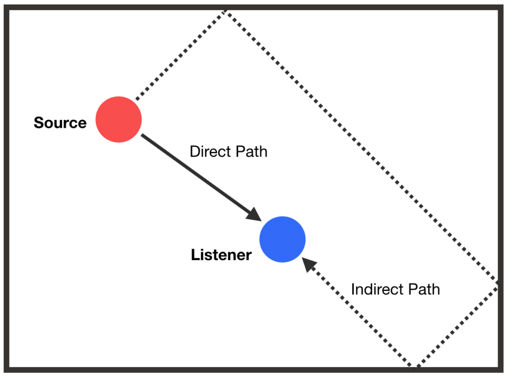
In an anechoic room, the number of indirect paths is minimized so the listener would only (theoretically) hear sound from the direct path, giving a dry perception. However, if a room allows for many sound wave reflections, the listener would hear many echos from many indirect paths and would perceive the room as reverberant. The amount of echos created is also referred to as echo density.
Compared to a sound wave from the direct path, a sound wave reaching the listener from an indirect path is generally quieter and reaches the listener later. As we will see, these properties are key in modelling reverberant rooms.
The Schroeder Reverberator
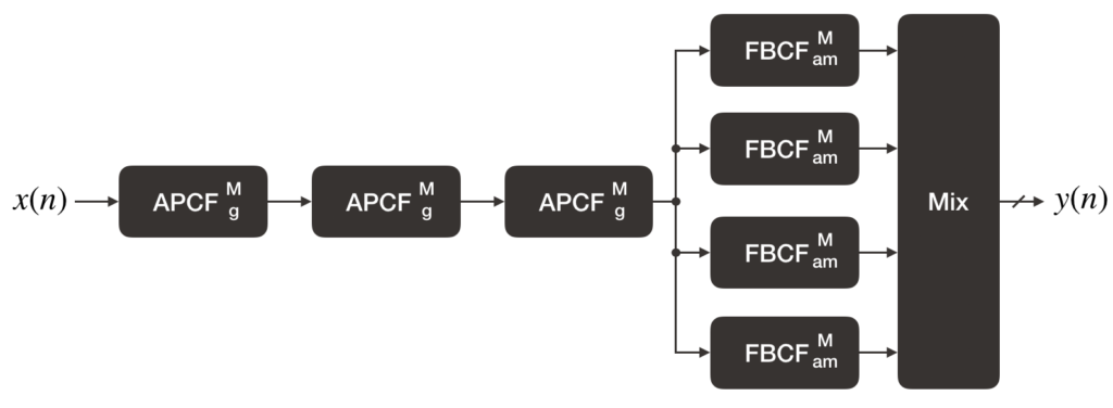
The above block diagram shows one of the basic forms of a Schroeder Reverberator as discussed in Smith’s book, Physical Audio Signal Processing, and is the design that will be implemented here. This type of reverberator was one of the early digital reverberator designs created by Manfred Schroeder in the 1960s. Since then, other designs (such as those using the Feedback Delay Networks) have gained popularity.
The Schroeder Reverberator consists of three main parts: an all-pass filter section, feedback filter section and a mixing matrix. Schroeder’s original design actually puts the feedback filter section before the all-pass filter section but it is mathematically equivalent to the design that we see here.
M, g, and am refer to the delay length and gain parameters of the filters respectively.
All-Pass Filter Section
Note that in the previous post, when the delay length of an all-pass comb filter (APCF) was increased, echos could be heard. This property of APCFs is used to build up the echo density needed for a reverberant effect.
Feedback Filter Section
The bank of feedback-comb filters (FBCF) emulates a room’s acoustic characteristics i.e. the effect of sound waves bouncing between the walls and the exponential decay of the echos over time.
Mixing Matrix
In a system with multiple speakers, the mixing matrix is especially useful to decorrelate the reverberator output for each channel.
Further information about the Schroeder Reverberator and its design equations can be found in the resources section below.
Implementation
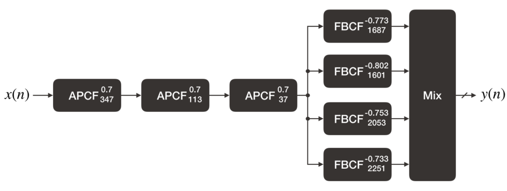
The following Schroeder Reverberator with specific parameters (also taken from the Physical Audio Signal Processing book) will be implemented using the DelayLine and CombFilter structs and functions created in the previous posts.
Note that much of the setup code needed to read and write audio samples are omitted for brevity. The full code is available on Github.
Friendly reminder: Before running audio code, always make sure to have your volume turned down or headphones off in case of any unexpected loud noises
//  main.c

//  ...
#include "DelayLine.h"
#include "CombFilter.h"

//  ...
#define NUM_BUFFERS 4
#define BUFFER_SIZE 2048
#define QUEUE_SIZE (NUM_BUFFERS)

#define NUM_APCFS 3
#define NUM_FBCFS 4

//  ...
float32_t fs = 30000.f;


//  Declare comb filters and parameters for Schroeder Reverberator
APCF *ap[NUM_APCFS];
FBCF *fb[NUM_FBCFS];

size_t APDelayLengths[NUM_APCFS] = {347, 113, 37};
float32_t APGain = 0.7f;
size_t FBDelayLengths[NUM_FBCFS] = {1687, 1601, 2053, 2251};
float32_t FBGains[NUM_FBCFS] = {0.773f, 0.802f, 0.753f, 0.733f};

//  ...
//  Function to shift in a sample into the Schroeder Reverberator and get the next output
int shiftSchroederReverberator(float32_t *x, float32_t *y)
{
  //  Shift in the audio input into the APCF section
  float32_t filterInput = *x;
  for (int i = 0; i < NUM_APCFS; ++i)
    apcfShift(ap[i], filterInput, &filterInput);

  //  Shift in result of the APCF section to the FBCF bank
  //  Also apply the mixing matrix to the output of the FBCF bank
  float32_t sum = 0.f;

  for (int i = 0; i < NUM_FBCFS; ++i)
  {
    float32_t fbcfOut = 0.f;
    fbcfShift(fb[i], filterInput, &fbcfOut);

    sum += fbcfOut;
  }

  *y = sum;

  return 0;
}


void deleteSchroederReverberatorFilters()
{
  for (int i = 0; i < NUM_APCFS; ++i)
    deleteAPCF(ap[i]);

  for (int i = 0; i < NUM_FBCFS; ++i)
    deleteFBCF(fb[i]);
}
Here, we declare the APCFs and FBCFs as global variables. Filter parameters are placed in arrays, with each element corresponding to a particular filter. For reasons explained later, the sampling frequency is set to 30 kHz instead of 40 kHz as in previous posts.
The process of shifting samples into the reverberator and getting the output is done in shiftSchroederReverberator. This function calls the shift function of each of its comb filter components. Applying the mixing matrix is also done here. However, since we are only using one audio channel, only one of the mixing matrix’s possible outputs are used. For a proper stereo output, you should use two of the matrix’s possible outputs. The equations for these outputs can be found in the Physical Audio Signal Processing book.
One important thing to be careful of is that in the all-pass section, the inputs to the all-pass filters are either the reverberator input or the output of the previous all-pass filter whereas the input to all the feedback filters is the output of the last all-pass filter.
Since we are allocating memory for the filters, it is important that we free the resources when we are done with them. deleteSchroederReverberatorFilters does this for us.
Initializing the filters and calling shiftSchroederReverberator is done in the main function:
int main(void)
{
  //  ...
  //  Allocate and initialize the comb filters here
  for (int i = 0; i < NUM_APCFS; ++i)
  {
    ap[i] = createAPCF(APDelayLengths[i], -APGain, APGain);
    if (ap[i] == NULL)
    {
      deleteSchroederReverberatorFilters();
      return 0;
    }
  }

  for (int i = 0; i < NUM_FBCFS; ++i)
  {
    fb[i] = createFBCF(FBDelayLengths[i], 1.f, -FBGains[i]);
    if (fb[i] == NULL)
    {
      deleteSchroederReverberatorFilters();
      return 0;
    }
  }

  //  ...
  while (1)
  {
    //  Check to make sure there is a buffer available for processing
    if (processingQueue[processingQueueHead] != NULL)
    {
      //  Shift audio data into the Schroeder Reverberator and get its output
      for (int i = 0; i < BUFFER_SIZE; ++i)
        shiftSchroederReverberator(&processingQueue[processingQueueHead][i], &processingQueue[processingQueueHead][i]);

      transferBufferToQueue(processingQueue[processingQueueHead], dacQueue, &dacQueueTail);

      processingQueue[processingQueueHead] = NULL;
      processingQueueHead = (processingQueueHead + 1) % QUEUE_SIZE;
    }
  }

  //  Remember to release any memory that you've allocated!
  deleteSchroederReverberatorFilters();
}
Note that shiftSchroederReverberator is called for each audio sample in the processing buffer. This makes for an expensive computation that our 48 MHz system probably can’t handle with the way the code is written now. This is why we will need to set compiler optimizations to speed things up.
Setting compiler optimizations can be done by going into the project properties then clicking C/C++ Build > Settings > GNU ARM C Compiler > Optimization. Click Optimize most (-O3) in the Optimization Level drop down box:
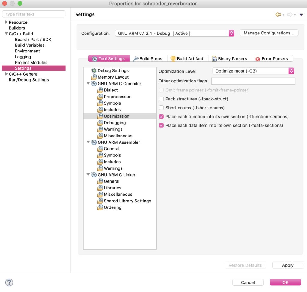
It turns out that even enabling compiler optimizations will cause our system to choke. For this reason, we lower the sampling frequency to afford us a bit more processing time.
There are ways to optimize our reverberator further which we will touch on in a different post.
How it Sounds
The sound is…well, not great but it definitely is reverberant. The reverberator gives a “metallic” quality to the audio clip. It’s almost more similar to a plate reverberator than a “natural room.”
Some of the more major problems with the sound quality stem from the fact that we are using only a 12-bit ADC and DAC (the effective number of bits is probably less) whereas more specialized audio systems will typically use converters with higher bit depths. The development board also contributes noise into the audio which can be very distinctly heard.
There are also physical modelling considerations that the Schroeder Reverberator does not factor into account but are addressed by other reverb designs. We will perhaps explore these in later posts.