
Hardware Setup
There are a lot of musically savvy engineers who, after their first signal processing course, use their newfound knowledge to build an effects pedal of sorts. I definitely put myself in this category.
Over the next while, I will be messing around with different audio processing methods like filtering, reverberation, wavetables and whatever I feel like playing around with.
For this post, I am going to go through the hardware setup. The firmware setup will be covered in the next post.
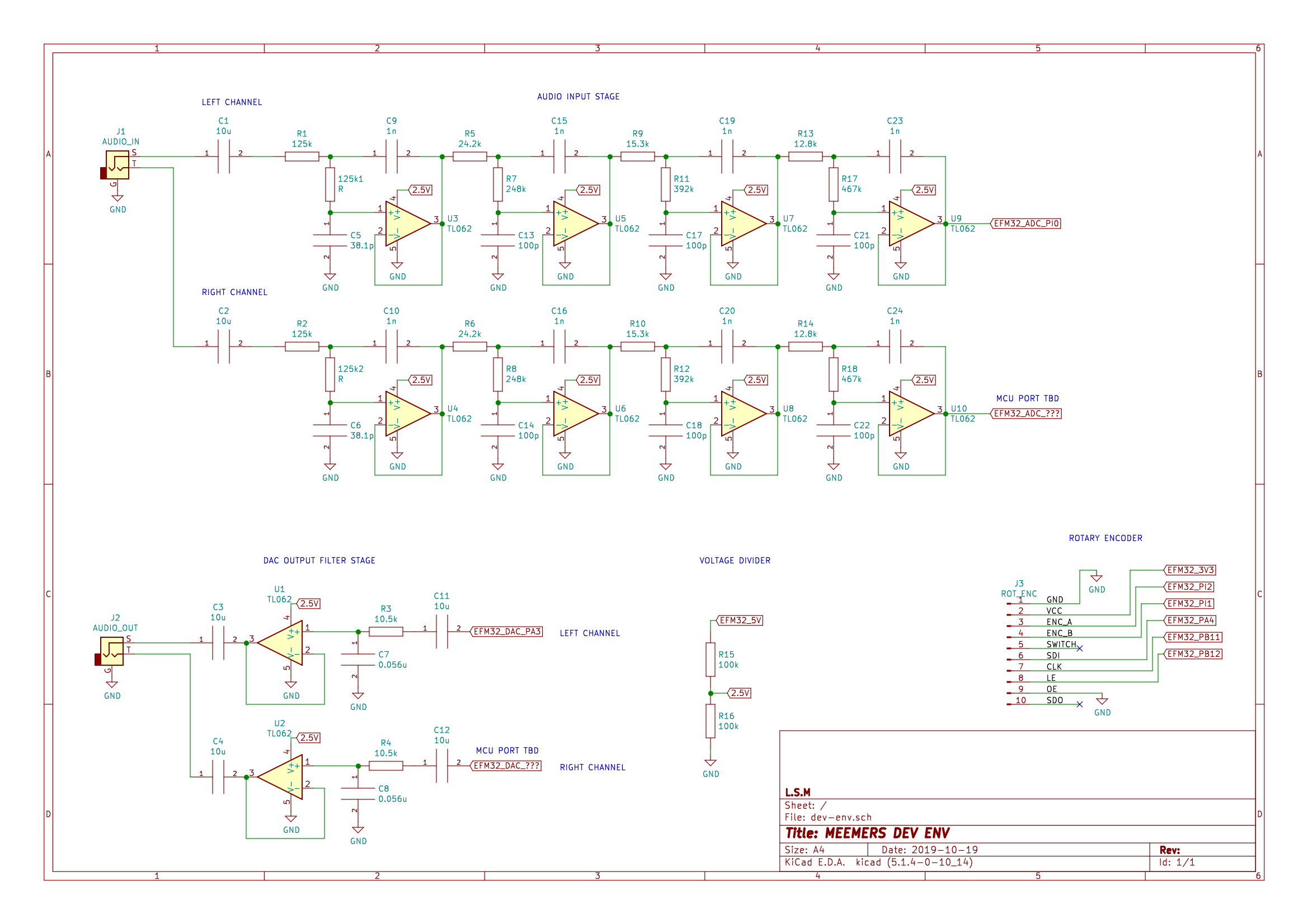
The analog front end schematic and a physical implementation example is provided below.

Development Board
I am using the Silicon Labs EFM32 Pearl Gecko Starter Board. While it is a little pricey (~100 USD), there’s a lot to like about it. It comes with an LCD screen, plenty of pin breakouts, buttons, capsense pads and perhaps most relevant, a built-in ADC and DAC.
As an added bonus, the EFM32 PG12 includes an ARM Cortex M4 core with a dedicated floating point unit (FPU) that will speed up our computations. Using an ARM core also allows us to take advantage of the CMSIS DSP libraries that should give us an extra processing boost.
Anti-alias Filter
This is a key component when sampling real-world, continuous signals. You want to ensure that frequency components higher than half of the sampling frequency (fs) are removed before entering the ADC.
There are plenty of textbooks and websites that dive into the details of aliasing. Chapter 2 of Understanding Digital Signal Processing by Richard G. Lyons is a pretty good reference.
While you can also combat aliasing by oversampling and applying digital filtering, I opted to use an analog low-pass filter (LPF) in favour of additional margin for processing time – something that will become evident when applying spectral signal processing techniques
Plugging in the below design parameters into the ADI Filter Wizard yields the following circuit:
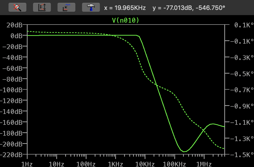
- fc (-3dB) = 6.5 kHz
- Butterworth response
- Stopband (12-bit ADC) = 73 dB @ 20 kHz
The minimum stopband level is based on the number of bits that your ADC has. Essentially, your input voltage must register as less than 1 bit for frequencies greater than half of fs (aka Nyquist Frequency). For a 12-bit ADC, 1 LSB = 1/(2^12) = 0.244 or 20log(0.244) = -72.24 dB. Rounding the result to the next integer value gives -73 dB.
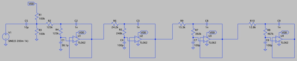
This circuit uses the Sallen-Key topology to implement an 8th order Butterworth filter. The resistor divider network at the filter input (far left) biases the input signal to about 2.5 V so that the ADC does not read negative signal swings as 0 LSB
I chose a Butterworth response due to its flat response in its passband. The cost to this design is attenuation in the 6.5 kHz – 20 kHz region (which are still audible frequencies). Honestly, this isn’t really desirable and at the cost of passband ripples, more filter stages and/or faster sampling, the response can be improved.
DAC Filter
After processing input samples, the MCU writes output samples to the digital-analog converter (DAC). Since the samples are written in discrete steps over time, the output waveform is going to have a ‘jagged’ look as the DAC jumps in value from one sample to another.
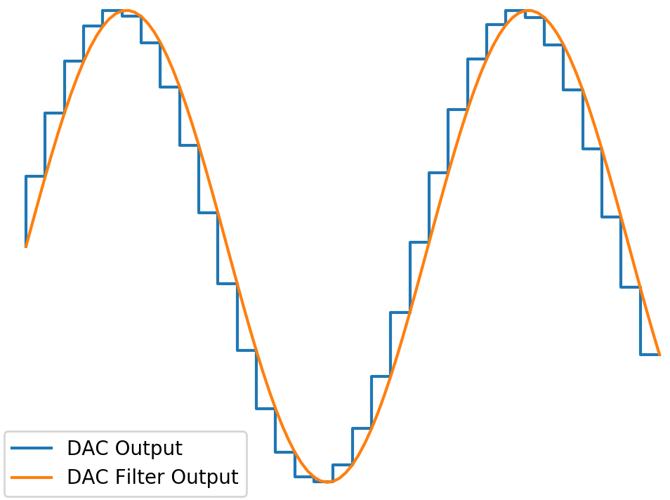
For those familiar with Fourier analysis, another way to view the problem is that higher frequency components are needed to reproduce the sudden jumps between time steps . By ‘filtering’ out these higher frequencies, you effectively smoothen the waveform.
To smooth out the waveform, a simple RC filter (fc = 2.7 kHz) is connected to the DAC. The cutoff frequency is completely arbitrary (and non-optimal) based off of components on-hand at the time.
To prevent output loads from affecting the filtered signal, a buffer is placed between the filter and output jack.
User Inputs
To modify input parameters to audio effects, I added a rotary encoder. This particular encoder uses the now discontinued LED and encoder breakout board from Mayhew Labs.
Audio Quality
This setup is by no means going to give you stellar audio quality. Apart from the sub-optimal analog filters, the breadboard and wiring will contribute noise into the audio signal. Also, some of the switching noise in the dev board voltage regulators will couple into the signal path resulting in a mildly annoying buzzing sound as you listen.
While the audio quality isn’t the best, it should be good enough to work with for now.