
Audio Buffers
In the previous post, we created a very basic example that read a sample of audio from some input and routed it directly to output. At a sample rate of 40 kHz, this sequence of events repeated every 25 usec.
This is fine, provided that any processing you do on the sample does not last longer than 25 usec. Apply any heavier processing however and you run the risk of having your audio sound something like this:
While this makes for an interesting effect, it’s probably an artifact that we don’t necessarily want. Let’s have a closer look at what’s happening.
Timing
The below diagram shows an ideal timeline of events when sampling and processing audio.
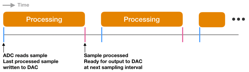
Each blue tick represents an interval of 25 usec. At each blue tick, the ADC reads a new sample and the previous sample (now processed) is sent to the DAC. Processing on the new sample also begins here. The pink ticks represent the point in time when processing finishes and the processed sample is ready to be transferred to the DAC (output).
The key point here is that processing finishes before the next sampling interval. Now let’s look at the non-ideal case:
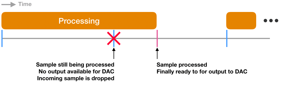
At the start, the ADC reads a new sample, data is written to the DAC and processing begins on the new sample just like in the ideal case.
However at the next tick, processing has not yet finished so the DAC cannot update the output with new data in a timely manner. Depending on the DAC configuration, it could hold the previous value or change to 0 (among other possibilities) thus distorting the desired output.
During this time, the ADC may not have a place to store the newly sampled data point, thus potentially dropping it.
Depending on how you’ve written your code and how your hardware is configured, distortions can manifest itself in different ways, including possibly deafening noises so be careful!
Buffering Samples
While there are a few ways around this problem, many systems will use a system of buffers to manage audio data.
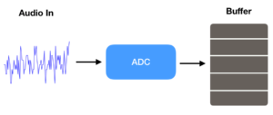
Instead of being sent directly to processing, the ADC places the sample into a buffer. Once filled, the buffer is transferred to processing and the ADC begins filling another empty buffer.
After processing, the buffer of processed data is sent to the DAC where it writes the buffer contents to output. When the DAC empties the buffer, it is sent back to the ADC and the whole process repeats. The result is a system where a series of buffers travel in a ring to each component.
The advantage of this system is that while a buffer of samples is processed, the DAC has a full buffer of previously processed data to output thus giving more time for processing and minimizing interruptions in audio.
Theoretically for this particular system, the extra time for processing is your sampling interval multiplied by the buffer size. If fs = 40 kHz and the buffer size is 256 samples wide then the allowed processing time is 6.4 msec.
This extra processing time however, comes at a cost. When the system first starts up, the buffer needs time to be filled and processed before the first audio output is written, thus resulting in a latency. For a buffer of size 256 samples and fs = 40 kHz, the latency, at minimum, would be 6.4 msec + processing time.
In practice, having only one buffer is still going to cause interrupted audio as the ADC will not have a buffer to write to after transferring the buffer it just filled, thus creating a gap in audio data. Creating at least 3 buffers plus one extra should be enough for the system to run smoothly.
Here, we chose 3 + 1 buffers because our system consists of three main parts: ADC, processing and DAC. The extra buffer gives us extra margin.
Implementation
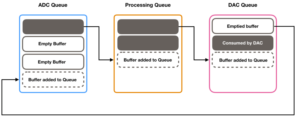
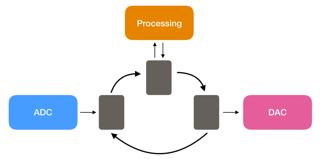
The above diagram illustrates the movement of audio data between the ADC, processing and DAC ‘blocks’.
Each block contains a queue of buffers that need attention. When a block finishes its work on a buffer, it is dequeued and transferred into the next block’s queue. The block will then focus on the next buffer in its queue.
At system startup, an ADC queue is filled with empty buffers ready to be filled with data. Once a buffer is filled, the buffer is transferred into the processing queue and the ADC block points to the next buffer in its queue to fill.
Likewise, in the processing queue, when a buffer is available for processing, the processing block will carry out its work and then transfer the buffer into the DAC queue once finished. After transfer, the processing block points to the next buffer in its queue to process. If there is no buffer available, the processing block will wait until it receives one.
While the processing block waits for a buffer, this does not mean that all the other blocks will halt and wait for the processing block since we are using a system of interrupts to give the illusion of ‘parallel processing.’
When a buffer of data is available in the DAC queue, the DAC will start consuming that data. Once the buffer is emptied, it transfers the emptied buffer back into the ADC queue and the DAC block points to the next buffer in its queue to consume.
If there is no buffer available in the DAC queue after the emptied buffer is transferred, this likely means that the processing time is too long. To fix this, you can try a larger buffer size to buy more processing time or optimize your processing.
Now that we’ve illustrated the concept, let’s dive into the code.
Buffer and Queue Setup
#define NUM_BUFFERS 4
#define BUFFER_SIZE 256
#define QUEUE_SIZE (NUM_BUFFERS)

//  Create buffers
volatile static float32_t buffer[NUM_BUFFERS][BUFFER_SIZE];

//  Create queues
volatile static float32_t *adcQueue[QUEUE_SIZE];
volatile static float32_t *processingQueue[QUEUE_SIZE];
volatile static float32_t *dacQueue[QUEUE_SIZE];

//  Create pointers to available buffers and available slots in each respective queue
volatile static uint32_t adcQueueHead = QUEUE_SIZE - 1;
volatile static uint32_t adcQueueTail = QUEUE_SIZE - 1;
volatile static uint32_t processingQueueHead = QUEUE_SIZE - 1;
volatile static uint32_t processingQueueTail = QUEUE_SIZE - 1;
volatile static uint32_t dacQueueHead = QUEUE_SIZE - 1;
volatile static uint32_t dacQueueTail = QUEUE_SIZE - 1;

int main(){

  //  Initialize buffers with all 0s
  for (int i = 0; i < NUM_BUFFERS; ++i)
    arm_fill_f32(0.0, (float32_t *)buffer[i], BUFFER_SIZE);

  //  Initialize all slots in each queue to NULL pointers
  //  Except for the adcQueue.  That queue should contain all the empty buffers
  for (int i = 0; i < QUEUE_SIZE; ++i){
    adcQueue[i] = buffer[i];
    processingQueue[i] = NULL;
    dacQueue[i] = NULL;
  }
}
Here, the buffer and queue sizes are specified and based on this information, we create and initialize them. As a starting point, all of the buffers are placed into the ADC queue.
Note that the queues are an array of pointers (memory addresses) to the buffers and not containers of actual audio data!
The head pointers keep track of the buffer currently in use while the tail pointers keep track of the next available empty slot in the queue where an incoming buffer can be transferred to. This will become more clear in the following sections.
ADC Block
The following block of code takes place in the ADC ISR:
void ADC0_IRQHandler(){

  //  Necessary interrupt flag clears here

  //  Check to make sure there is an empty buffer available
  if (adcQueue[adcQueueHead] != NULL){
    adcQueue[adcQueueHead][adcBufferIndex] = (float32_t)ADC0->SINGLEDATA;
    adcBufferIndex++;

    if (adcBufferIndex >= BUFFER_SIZE){
      adcBufferIndex = 0;

      transferBufferToQueue(adcQueue[adcQueueHead], processingQueue, &processingQueueTail);

      adcQueue[adcQueueHead] = NULL;
      adcQueueHead = (adcQueueHead + 1) % QUEUE_SIZE;
    }
  }
}
After the ADC reads an audio sample, it writes that sample to the buffer in the ADC queue pointed to by adcQueueHead. adcBufferIndex specifies the slot in the buffer where the sample is written to.
Once the buffer is filled, the ISR calls transferBufferToQueue() to transfer the full buffer into the processing queue. processingQueueTail specifies which slot in the processing queue the buffer is to be transferred.
Once the buffer has been transferred to the next queue, the slot where the buffer used to be is set to NULL to signify that there is no buffer assigned to that slot. adcQueueHead is incremented to the next slot in the queue which (hopefully) contains another empty buffer to fill.
Note that the queue is a circular structure. When adcQueueHead or adcQueueTail is incremented past the last index, it is wrapped back around to index 0.
Processing Block
Buffer and queue handling in the processing block is similar to the ADC block. To avoid spending too much time in the ISRs, the processing block is placed in the main infinite loop.
int main(){

  //  Hardware initializations here
  //  Buffer and queue initializations here

  while(1){

    //  Check to make sure there is a buffer available for processing
    if (processingQueue[processingQueueHead] != NULL){

      //  Fancy processing code here

      transferBufferToQueue(processingQueue[processingQueueHead], dacQueue, &dacQueueTail);

      processingQueue[processingQueueHead] = NULL;
      processingQueueHead = (processingQueueHead + 1) % QUEUE_SIZE;
    }
  }
}
DAC Block
Again, buffer and queue handling in the DAC block is similar to the previous blocks but we will include it here for completeness.
void TIMER0_IRQHandler(){

  //  Necessary flag clears here
  //  Code to initialize ADC sampling here

  //  Check to make sure there is a buffer to consume
  if (dacQueue[dacQueueHead] != NULL){

    //  Write an output sample to DAC
    VDAC_Channel0OutputSet(VDAC0, (uint32_t)dacQueue[dacQueueHead][dacBufferIndex]);

    dacBufferIndex++;

    if (dacBufferIndex >= BUFFER_SIZE){

      dacBufferIndex = 0;
      transferBufferToQueue(dacQueue[dacQueueHead], adcQueue, &adcQueueTail);

      dacQueue[dacQueueHead] = NULL;
      dacQueueHead = (dacQueueHead + 1) % QUEUE_SIZE;
    }
  }
}
In this case, when the buffer is emptied, it is sent back to the ADC queue in the slot pointed to by adcQueueTail.
Let’s have a closer look at the transferBufferToQueue() function:
void transferBufferToQueue(volatile float32_t *outgoingBuffer, volatile float32_t **ingoingQueue, volatile uint32_t *ingoingIndex){

  //  If the slot pointed to by ingoingIndex is NOT NULL, it means that it is already occupied by a buffer
  if (ingoingQueue[*ingoingIndex] == NULL){
    ingoingQueue[*ingoingIndex] = outgoingBuffer;

    *ingoingIndex = (*ingoingIndex + 1) % QUEUE_SIZE;
  }
}
The function expects the following: what buffer you want to transfer (outgoingBuffer), where that buffer is going (ingoingQueue) and which slot it needs to go (ingoingIndex). At the start, there is a quick check to make sure that the slot isn’t already occupied by an existing buffer.
The code presented here for buffer transfer operations could be more generalized. There are also a lot of edge cases that are not mitigated – for instance, what happens when a queue overflows? Or what happens when a slot in the queue that an ingoing buffer is going to is already occupied? These things should be considered when creating a more serious implementation of buffers. The code provided here exists to simply illustrate the concept.
This rather lengthy post should give you a basic idea of how to buy more processing time in exchange for latency. How much latency is tolerable really depends on the type of your application. This video should give you an idea of acceptable tolerances. An audio pass-through example using buffers is available on Github.