
Audio Pass-Through
The first couple of posts went through setting up the hardware and the development environment. In this post, we’re going to make use of what we’ve learned so far and create a simple audio pass-through unit.
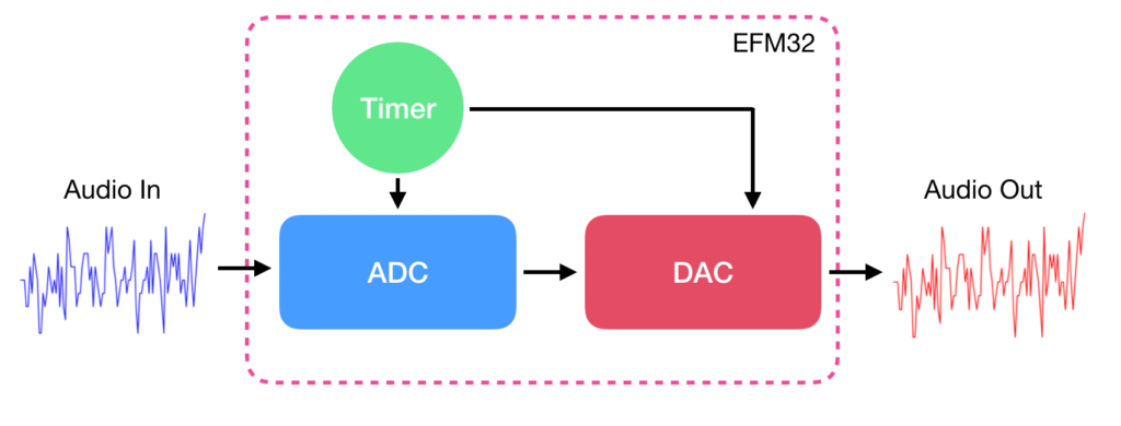
The above diagram describes the signal flow and the peripherals needed. More complicated systems will have an additional ‘processing block’ between the ADC and DAC but since we’re not going to be doing anything fancy this time, we’re going to leave that block out.
While you may not need to for this example, reading the Pearl Gecko reference manual and data sheet is highly recommended in order to get a deeper understanding of the MCU and its peripherals.
Timer
Timers are important to making sure that audio samples will be taken in regular, consistent intervals.
We will use a sampling frequency of fs = 40000 Hz or an interval of 25 usec. Using the default HFPERCLK_TIMER clock frequency of 40 MHz (for the Pearl Gecko dev board), a 25 usec period corresponds to 1000 clock pulses.
After every 1000 pulses, we want the timer to trigger an interrupt so that we can sample the input signal. By setting the top value of the timer counter to 1000, the timer will raise an interrupt when the counter overflows. The setup code looks something like this:
static void setupSamplingTimer(){

  //  Enable clocks to Timer
  CMU_ClockEnable(cmuClock_TIMER0, true);

  //  Configure the timer
  //  We want an up-counting timer that goes up to a value that corresponds to 25 usec
  //  For a 40 MHz clock (no prescaling), that value is 1000
  TIMER_Init_TypeDef init = TIMER_INIT_DEFAULT;

  //  Don't start the timer after initialization yet
  init.enable = false;

  TIMER_Init(TIMER0, &init);

  //  Calculate the number of pulses needed for each sampling period
  float32_t samplingPeriod = 1 / 40000.0f;
  float32_t numPulsesf =   samplingPeriod * 40000000.0f;
  uint32_t numPulses = (uint32_t)numPulsesf;

  //  Set counter limit
  TIMER_TopSet(TIMER0, numPulses);

  //  Enable overflow interrupt
  NVIC_EnableIRQ(TIMER0_IRQn);
  TIMER_IntEnable(TIMER0, TIMER_IF_OF);
}
The EMLIB library provides interfaces that make it more convenient to setup peripherals. In this case, a lot of the register settings can be done via a TIMER_Init_TypeDef variable, where it can then be passed into TIMER_Init().
The Pearl Gecko has many timer modules but in this case, we are going to make use of TIMER0 to drive our sampling intervals.
ADC
Let’s have a look at the ADC code.
static void setupADC(){

  //	Enable clock to ADC
  CMU_ClockEnable(cmuClock_ADC0, true);

  ADC_Init_TypeDef init = ADC_INIT_DEFAULT;

  init.timebase = ADC_TimebaseCalc(0);
  init.prescale = ADC_PrescaleCalc(10000000, 0);

  ADC_Init(ADC0, &init);

  ADC_InitSingle_TypeDef sInit = ADC_INITSINGLE_DEFAULT;

  //	Setup single channel mode parameters
  sInit.reference = adcRefVDD;
  sInit.acqTime = adcAcqTime8;          //  Take 8 ADC clock cycles to capture sample
  sInit.posSel= adcPosSelAPORT0XCH0;    //  ADC Input = Port PI0
  sInit.negSel = adcNegSelVSS;	        //  Single-ended ADC input
  sInit.rep = false;                    //  Disable repeated mode

  ADC_InitSingle(ADC0, &sInit);

  NVIC_EnableIRQ(ADC0_IRQn);
  ADC_IntEnable(ADC0, ADC_IF_SINGLE);
  ADC_IntEnable(ADC0, ADC_IF_SINGLEOF);
}
Lines 4 – 11 configure the peripheral clock and ADC timing parameters. The prescale is set such that the ADC clock is 10 MHz (it’s max allowed rate). More information about timebases can be found in the reference manual.
To sample the audio signal, we are going to use the ADC in single channel mode as opposed to scan mode. Scan mode may be more appropriate when working with more than one audio channel.
Note that a lot of the ADC configurations are handled through the ADC_Init_TypeDef and ADC_InitSingle_TypeDef variables which are then passed into their respective Init functions.
The reference voltage or, the voltage that corresponds to the ADC max value (4096 in this case) is set to VDD (3.3 V)
As our audio channel is single-ended, the ADC’s inverting input is grounded while the non-inverting input is connected to the audio signal line via APORT0XCH0 (PI0 for the EFM32 dev board).
DAC
The last peripheral to go over is the VDAC (Voltage DAC), which will convert a processed number into a physical voltage that is eventually routed to some output. Let’s have a look at the initialization:
static void setupDAC(){
  //	Enable VDAC clock
  CMU_ClockEnable(cmuClock_VDAC0, true);

  VDAC_Init_TypeDef vdac_init = VDAC_INIT_DEFAULT;
  VDAC_InitChannel_TypeDef vdac_init_channel = VDAC_INITCHANNEL_DEFAULT;

  vdac_init.prescaler = VDAC_PrescaleCalc(1000000, true, 0);
  VDAC_Init(VDAC0, &vdac_init);

  vdac_init_channel.enable = true;
  VDAC_InitChannel(VDAC0, &vdac_init_channel, 0);
}
The initialization is essentially identical to the setup example provided in the EMLIB documentation. Since we are only using the DAC at its most basic level, a simple setup is all we really need.
Again, the Pearl Gecko has more than one VDAC peripheral but we will be using VDAC0 routed to its default pin, PA3.
Note that for the Pearl Gecko, the max clock frequency that the DAC can support is 1MHz, so when using a peripheral clock of >1 MHz, you will need to prescale the clock. EMLIB provides a convenient function, VDAC_PrescaleCalc() to determine the prescaling divider.
While we were initializing the peripherals, you may have noticed a pattern emerging. Most peripheral initializations will involve enabling the peripheral clock, setting registers with a wrapper typedef, feeding the typedefs into initialization functions and then finally enabling interrupts:
//  Peripheral basic initialization pattern
void setupPeripheral(){

  enable_peripheral_clock();

  Peripheral_typedef init;
  init.register_setting_x = value;

  Peripheral_Init(&init);

  NVIC_EnableIRQ(Peripheral_IRQ);
  Peripheral_IntEnable(Int_Flag);
}
Interrupts will likely be a topic for another post as the ARM processor and the Gecko SDK have their own ways for setting up interrupts.
Putting it all Together
With the initializations out of the way, we can finally get to the main program flow.
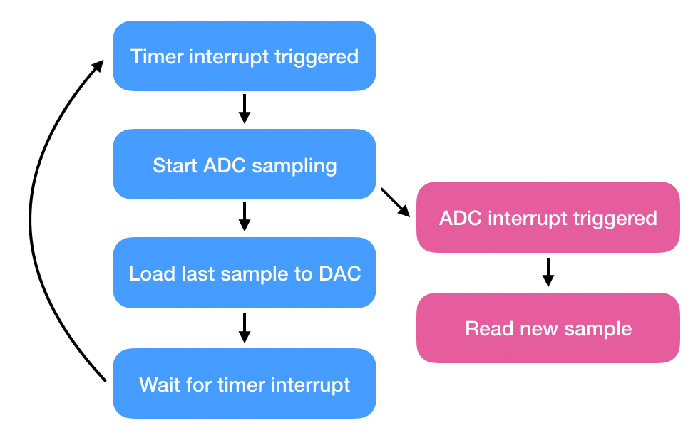
Judging from the flowchart, this program is going to be mainly interrupt driven. Every 25 microseconds (1/40000Hz), the timer is going to generate an interrupt. During the interrupt service routine (ISR), we are going to kick off the ADC sampling and then write the last read sample to the DAC.
The time needed for sampling is <25 usec so the ADC should finish sampling long before the next timer interrupt is triggered.
A standard rule that I consistently see in audio processing is that if the time taken for processing is not deterministic, then it should not be included in the program.
The following is an implementation of the program flow:
#include "em_device.h"
#include "em_chip.h"
#include "em_cmu.h"
#include "em_timer.h"
#include "em_adc.h"
#include "em_vdac.h"
#include "arm_math.h"

volatile uint32_t sampleValue;

// Initialization code would be here...

int main(void)
{
  /* Chip errata */
  CHIP_Init();

  setupSamplingTimer();
  setupADC();
  setupDAC();

  TIMER_Enable(TIMER0, true);

  /* Infinite loop */
  while (1);
}

//  Your ISR functions MUST be named as such
void TIMER0_IRQHandler(){

  //  Clear interrupt flags
  TIMER_IntClear(TIMER0, TIMER_IFC_OF);

  //  Kick off ADC sampling
  ADC_Start(ADC0, adcStartSingle);

  //  Write last sample value to DAC
  VDAC_Channel0OutputSet(VDAC0, sampleValue);
}

//  ISR for when ADC finishes sampling
void ADC0_IRQHandler(){
  sampleValue = ADC0->SINGLEDATA;
}
In the ADC ISR, SINGLEDATA is the ADC register that stores the sampled value which is then assigned to the variable, sampleValue. Note that sampleValue is declared as volatile. This tells the compiler that, when optimizing, it should consider that this variable has the potential to change outside of the regular program flow. More information can be found here.
This program is a far cry from a GOOD program but it should suffice in illustrating the concept. If you plan to add further processing with this code, then note that your processing will have to finish in under 25 usec (best case scenario) otherwise you run the risk of dropped samples. Programs will typically use buffers to process batches of data which will afford you extra processing time in exchange for latency.
This example should give you a place to start for delving into embedded audio processing. The source code is available on Github. Provided that you have an appropriate analog front end (like the one in this post) and you are using the Pearl Gecko dev board, if you make the necessary connections and run the program, you should hear whatever audio source you are connected to.
Before running any code on your dev board, be sure to first remove your headphones from your head or unplug your speakers (or whatever is connected to your output) to protect your ears from any unexpected surprises ranging from a startling pop to eardrum damaging sounds.